CHAPTER - 8
SANDWICH STRUCTURES
8.1 BASIC CONCEPT
8.2 FACE, CORE AND ADHESIVE MATERIALS
8.3 SANDWICH LAMINATED PLATE THEORY
8.4 SYMMETRIC ORTHOTROPIC SANDWICH LAMINATED PLATES
8.4.1 Bending under Transverse Load q
8.4.2 Transverse Vibration and Buckling
8.5 UNSYMMETRIC ORTHOTROPIC SANDWICH LAMINATED PLATES
8.7 BIBLIOGRAPHY
8.8 EXERCISES
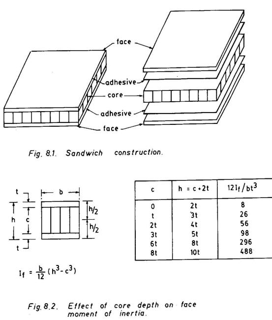
A sandwich structural element is essentially a composite construction, where a relatively thick core layer of low strength, stiffness and density is sandwiched between two thin, face layers of strong and dense materials (Fig. 8.1). In this three-layered
Fig. 8.1
construction, the faces and the core along with the adhesive layer have got some distinct roles to play. The main function of the core is to keep the faces apart and stablise them. To this effect, however, the core must possess a certain shear rigidity in planes perpendicular to the faces, being thin but made of much stronger and stiffer materials, resist the main part of the stresses developed in their own planes under action of external forces. In fact, the faces are finally responsible for bearing the loads of structural sandwiches, while the core enables the faces to act accordingly. In this repect, the role played by the adhesive is most vital, as it ensures the composite action of the sandwich system as a whole. Once the adhesive fails, the sandwich action is lost and the faces merely behave as two independent thin members.
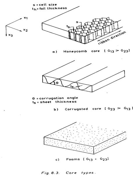
The main advantage of a sandwich construction is primarily derived from the fact that, as face sheets are separated further and further apart the moment of inertia of faces (If) about the mid-plane of the sandwich increases considerably, although there may be a marginal increase in weight (normally 5-10%) due to the higher thickness of the core. This is illustrated in Fig. 8.2. The behaviour resembles as that of a I section. With the increase of c, If increases at a much higher rate, although the face thickness t remains unchanged. A higher moment of inertia If in conjunction with a higher face modulus Ef may provide very high flexural rigidity (Ef If) against lateral bending, buckling and vibration.
Fig. 8.2
Further in a sandwich construction, various materials can most efficiently be combined together not only to derive the desired structural rigidity but also to achieve improved heat resistance acoustic insulation, vibration isolation, shock resistance and several other properties.
8.2 FACE, CORE AND ADHESIVE MATERIALS
The aluminium alloys, magnesium alloys, titanium alloys, stainless steel and structural composities are commonly used face materials for primary structural components. The ply wood, gypsum and paper boards, plastic laminates and similar other materials are also used as face layers in sandwich construction.
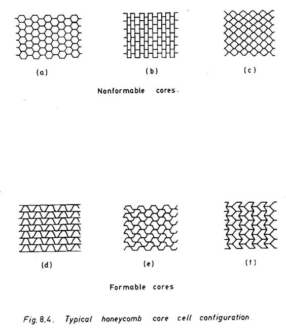
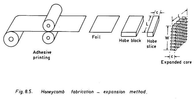
The most common cores are of honeycomb (cellular) type (Fig. 8.3a). They may be either formable or nonformable (Fig. 8.4). The formable honeycomb cores permit some amount of out-of-plane bending so that they can be employed to fabricate curved structural elements. A honeycomb core of the desired cell size (normally varies between 4-12 mm) is fabricated with very thin layers (foils) of sheet materials of aluminium alloys, titanium alloys, resin impregnated draft paper, plastic film and polymer composites. The honeycomb foil thickness, th usually ranges between 20-150µm.
Fig. 8.3
Fig. 8.4
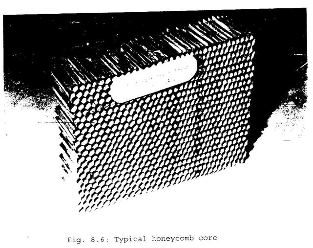
The cores are fabricated either using expansion method or corrugation method. The expansion method, is however, very common. It is schematically illustrated in Fig. 8.5. A typical expanded core is shown in Fig. 8.6. Figure 8.7 exhibits the node to node bond test of a honeycomb core. The honeycomb core exhibits higher transverse properties (G13 > G23) along the ribbon directions. A corrugated core (Figs. 8.3b and 8.8) can also be made out of similar materials as those used for making honeycomb cores. The thickness ts, in this case, is normally higher than 200µm. In the case of a corrugated core (G23 > G13), the
Fig. 8.8
corrugation also provides an additional amount of bending rigidity about the x2-axis. The other core materials are foams in the form of expanded plastics (e.g., PVC, Phenolic Polyurethene, Polystyrene, etc.), foamed glass, foamed aluminium and so on. As the air bubbles are uniformly dispersed within a foam material, it exhibits an isotropic behaviour (G13 = G23). The balsa wood has also been used as a core. The airframe of the Mosquito Bomber of World War II frame was of sandwich construction with birch wood faces and balsa wood core.
The density of conventional core materials may vary between 0.025-0.35 gm/cc. The transverse shear rigidity may be as low as 4000 Pa in the case of a foamed plastic or as high as 1 MPa in the case of a honeycomb core. A plate shear test (Fig. 8.9) is normally used to determine the transverse shear properties of the core.
Fig. 8.9
The adhesive are either in the form of liquids and pastes or films. Modified epoxies, polyimides, nitrile phenolics and modified urethanes are commonly used in a sandwich construction. Sandwich adhesives should have a unique combination of surface-melting, bond line control and controlled flow during curing as well as excellent adhesion and better peel strength properties. The adhesion and peel strength properties of a core material are determined using lap shear and drum peel tests (Figs. 8.10 and 8.11).
Fig. 8.10
Fig. 8.11
8.3 SANDWICH LAMINATED PLATE THEORY
Here we develop the
governing differential equations for bending of a three layered sandwich plate
(Fig. 8.12). The plate is subjected to transverse load q per unit area of the
plate as well as edge loads ![]() per unit length. Note that
per unit length. Note that
![]() and w are mid-plane displacement components, and
and w are mid-plane displacement components, and
![]() are bending rotations. The following assumptions are made:
are bending rotations. The following assumptions are made:
1. The displacements are small.
2. The material behaviour is linear and elastic.
3. The faces are thin and may be of different materials (including general laminated composites) and thicknesses.
4. The core is thicker, and its behaviour resembles that of an antiplane core. An antiplane core contributes marginally towards the flexural rigidity of the sandwich plate. This is true in many practical sandwich structures, especially with honeycomb cores.
The transverse shear stiffnesses of the face materials are assumed to be infinite,while the core is shear flexible (i.e., for the core (G1z and G2z) are finite).
With above
assumptions, we may assume the Mindlin type of first order shear deformation
behaviour of the core, although one may generalize using higher-order shear
deformation theories. Thus, straight lines originally normal to the midsurface,
before deformation, remain straight but not normal to the deformed midsurface.
The actual rotation w,1 of a section perpendicular to the x1-axis
is resulted due to the rotation due to bending.
![]() (in which the normal remains perpendicular to the midsurface)
and a rotation
(in which the normal remains perpendicular to the midsurface)
and a rotation ![]() (
(![]() ) due to transverse shear. This is illustrated in Fig. 8.13.
Hence
) due to transverse shear. This is illustrated in Fig. 8.13.
Hence
![]()
![]()
and also
![]()
![]() (8.1)
(8.1)
![]()
Fig. 8.13
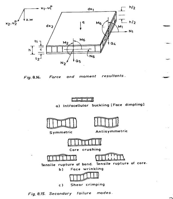
The force and moment resultants acting on the positive faces of an infinitesimally small plate element dx1dx2 are shown in Fig. 8.14. These are expressed in terms of midplane strains and curvatures as given by
 (8.2)
(8.2)
where
 i, j =1,2,6 (8.3)
considering both the faces and the core together as multi-layered laminate, and for the core
 (8.4)
(8.4)
where,
 i, j = 4,5
(8.5)
i, j = 4,5
(8.5)
and k44, k55 are shear correction factors.
For an antiplane core (e.g., honeycomb core)
![]() if the ribbon direction lies parallel to the x1-axis.
if the ribbon direction lies parallel to the x1-axis.
Also note that
![]()
![]() (8.6)
(8.6)
and
![]() are defined in Eq. 8.1.
are defined in Eq. 8.1.
Fig. 8.14
From the equilibrium of forces acting on the sandwich plate element (Fig. 8.14), the equations of equilibrium are derived as
![]()
![]()
![]() (8.7)
(8.7)
![]()
![]()
Substitution of Eqs.
8.1 through 8.6 in Eqs. 8.7 yields five differential equations of equilibrium,
in terms of five unknown displacements
![]() , w,
, w, ![]() . These are derived as follows:
. These are derived as follows:


 (8.8)
(8.8)


8.4 SYMMETRIC ORTHOTROPIC SANDWICH LAMINATED PLATES
Assume the case (e.g., similar cross-ply laminated faces and orthotropic honeycomb core) when A16 = A26 = D16 = D26 =S45 = 0 and due to symmetry Bij =0. The differential equations defined in Eqs. 8.8 reduce to

 (8.9)
(8.9)
The first two equations of Eqs.
8.9 are expressed in terms of ![]() only and are uncoupled with respect to w,
only and are uncoupled with respect to w,
![]() . The last three equations of Eqs. 8.9, which are expressed in
terms of w,
. The last three equations of Eqs. 8.9, which are expressed in
terms of w, ![]() , form the set of governing equations for the bending of
symmetric orthotropic sandwich laminated plates.
, form the set of governing equations for the bending of
symmetric orthotropic sandwich laminated plates.
8.4.1 Bending under Transverse Load q
The plate (Fig. 8.14)is assumed to be simply supported along all the edges. The simply supported plate boundary conditions are as follows:
![]()
![]() (8.10)
(8.10)
The solution given by
![]()
![]() (8.11)
(8.11)
![]()
satisfies boundary conditions defined in Eqs. 8.10.
![]() (8.12)
(8.12)
Substitution of Eqs. 8.11 and
8.12 in the last three equations of Eqs. 8.9 (![]() results in three algebraic equations in terms of
results in three algebraic equations in terms of
![]() given as follows:
given as follows:
 (8.13)
where,
 (8.14)
Solving these equations, we
obtain ![]() in
terms of qmn where qmn for a specific transverse load q(x1x2)
is determined from Eq. 7.21. Substitution of
in
terms of qmn where qmn for a specific transverse load q(x1x2)
is determined from Eq. 7.21. Substitution of
![]() in Eqs. 8.11 yields the final solution of displacements
in Eqs. 8.11 yields the final solution of displacements
![]() and
w.
and
w.
8.4.2 Transverse Vibration and Buckling
For
transverse vibration, the last equation of Eqs. 8.9 is modified replacing 'q' by
'![]() ' and assuming
' and assuming ![]() . Note that
. Note that ![]() is the mass per unit area of the plate. The solution
is the mass per unit area of the plate. The solution
![]()
![]() (8.15)
(8.15)
![]()
satisfies the simply supported
boundary conditions (Eq. 8.10). Substitution of Eqs. (8.15) in the last three
equations (replacing 'q' by '![]() ' and
' and ![]() ) of Eqs. 8.9 yields a set of three homogeneous, algebraic
equations in terms of
) of Eqs. 8.9 yields a set of three homogeneous, algebraic
equations in terms of ![]() , as given by
, as given by
 (8.16)
where
![]() are defined in Eqs. 8.14 and
are defined in Eqs. 8.14 and
![]() is expressed as
is expressed as
 (8.17)
The frequency equation is
obtained from the condition that the determinant of the coefficients of
![]() is equal to zero. The buckling equation corresponds to the
case, when the frequency term vanishes.
is equal to zero. The buckling equation corresponds to the
case, when the frequency term vanishes.
8.5 UNSYMMETRIC ORTHOTROPIC SANDWICH LAMINATED PLATES
Consider a simply supported unsymmetric orthotropic sandwich laminated platem e.g., a sandwich plate with dissimilar cross-ply faces and a honeycomb core. Then,
![]() (8.18)
(8.18)
Substitution of Eqs. (8.18)
into Eqs. 8.8 yields five governing differential equation which are coupled with
respect to ![]() . Let the solution be
. Let the solution be
![]()
![]()
![]() (8.19)
(8.19)
that satisfy the simply supported boundary conditions as follows:
![]()
![]() (8.20)
(8.20)
Following the procedure described in section 8.4 the transverse bending, vibration and buckling problems can be solved.
The sandwich structures exhibit various secondary failure modes. Some of these failure modes may precede the primary failure due to bending and overall buckling. A few important secondary failure modes commonly observed in sandwich construction, are illustrated in Fig. 8.15.
Intracellular Buckling (Fig. 8.15a)
This is a localized mode of buckling failure, when the core is not supported by faces continuously as in the case of a honeycomb core. The supported face within a honeycomb cell may be regarded as a thin plate with the cell walls acting as edge supports. The intracellular buckling strength corresponds to the buckling stress, σcr of the face plate of cell sizes (Fig. 8.3a). In the case of a thin isotropic face, the critical intracellular buckling stress σcr is given by
 (8.21)
Here η is a plasticity correction factor for metallic faces and the suffix 'f ' relates to faces. Similar expressions for σcr for general laminated composite faces do not exist. However, one can compute the critical intracellular buckling stress for such cases using the analysis procedures described in chapter 7 or by employing the finite element analysis method (chapter 8).
Face wrinkiling (Fig. 8.15b)
This is also a localized mode of instability. It is not confined to individual cells of cellular type cores. Further it involves the transverse (normal to facings) straining of the core material. The faces wrinkle in the form of short wavelengths and finally lead to either crushing of the core or tensile rupture of the core and the core-facing bond. The antisymmetric form of wrinkling is normally encountered in a continuous or foam core. The cellular core usually causes symmetric wrinkling. For an isotropic face the critical wrinkling stress σwr is given as follows:
Antisymmetric wrinkling :
 (8.22)
Where Q = 0.5 provides the lower bound of test results. The suffix 'c ' refers to the core.
Symmetric wrinkling:
 (8.23)
Shear Crimping (Fig. 8.15c)
It is a special form of general (overall) instability in which the buckle wavelength is very short. This happens when the core possesses very low shear modulus. This phenomenon occurs quite suddenly and usually causes the core to fail in shear. It may also lead to the face-to-core debond.
Unaxial compression:
![]() (8.24)
(8.24)
Pure inplane shear :
![]() (8.25)
(8.25)
Fig. 8.15