CHAPTER - 5
TEST METHODS
5.1 INTRODUCTION
5.2 CHARACTERISATION OF PROPERTIES
5.2.1 Density
5.2.2 Fibre Volume Fraction
5.2.3 Fibre Tensile Properties
5.2.4 Matrix Tensile Properties
5.2.5 Tensile Properties of Unidirectional Lamina
5.2.6 Inplane Shear Properties
5.2.7 Compressive Properties of Unidirectional Lamina
5.2.8 Interlaminar Shear Properties
5.3 NDT METHODS
5.3.1 Acoustic Emission
5.3.2 Holographic Interferometry
5.3.3 Radiography
5.3.4 Thermography
5.3.5 Ultrasonics
5.4 BIBLIOGRAPHY
5.5 EXERCISES
Testing is a very broad and diverse discipline that concerns with the (i) characterization of physical, mechanical, hygral, thermal, electrical and environment resistant properties of a material, that are required as design input, (ii) quantification of inclusions, voids, cracks, delaminations and damage zones for design assessment, and (iii) testing and qualification for final product realization. Testing, at the final stage may also involve application of simulated service loads and exposure to accelerated environmental conditions. Testing, in fact, is a continuous process, it interacts with a product at every stage of its design and development and, in most cases, continues until the product ensures optimum performance requirements even after it is put to a certain period of continuous service.
The testing of composites is much more involved than that of most
other materials. The number of material parameters to be determined is quite
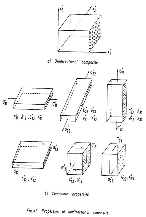
large. Take the case of a three-dimensional unidirectional composite (Fig. 5.1).
The mechanical parameters that are to be generated are three longitudinal moduli
(E'11, E'22 , E'33 ), three Poisson 's ratios
(ν '12 , ν '13, ν '23 , ), three shear moduli
(G'12, G'13, G '23) and nine strength constants
– six normal strengths (X'11, X'22, X '33, in
tension and compression) and three shear strengths (X'12, X'13,
X'23) and likewise ultimate tensile, compressive and shear strains.
Besides, there are important parameters, namely moisture diffusivities (d '11,
d '22, d '33), coefficients of moisture expansion (β'11,
β'22, β'33), maximum moisture content
![]() , thermal conductivities (K'11, K'22, K'33
), coefficients of thermal expansion α '11, α '22, α '33
), heat capacity ( C ) and several other parameters related to impact, fracture,
fatigue, creep, viscoelasticity, plasticity, strain-hardening, etc.
, thermal conductivities (K'11, K'22, K'33
), coefficients of thermal expansion α '11, α '22, α '33
), heat capacity ( C ) and several other parameters related to impact, fracture,
fatigue, creep, viscoelasticity, plasticity, strain-hardening, etc.
A specimen plays a vital role in realizing the desired test objective. The shape and size of a specimen and its test requirements vary from one test to the other. The heterogeneity and anisotropy of composites control the specimen design. A ' dog bone ' type specimen may be used for the tensile testing of a quasi-isotropic composite (particulate or randomly oriented short fibre composite) whereas a unidirectional composite requires a flat specimen with end tabs. A specimen to study the microstructure may need a Scanning Electron Microscope so as to obtain finer details of individual reinforcements, interfacial bonds, voids, micro-cracks, etc., on the other hand the testing of a proto-type aircraft composite wing component specimen may involve elaborate fixtures and instrumentations to simulate the load and measure the test data. All aspects of testing, namely, specimen preparation, design of test-rigs and fixtures, instrumentation and analysis of test data, are vital to the success of a test programme. The statistical allowables of the test data are normally based on
A-Basis: The A parameter value is the value above which at least 99% population of values is expected to fall with a 95% confidence level.
B-Basis: The B parameter value is the value above which at least 90% population of values is expected to fall with a 95% confidence level.
S-Basis: The S parameter value is the minimum value specified by the governing specifications.
Typical Basis: The typical parameter value is an average value. No statistical assurance is associated with this value.
It is to be remarked that the test procedures to determine all the intrinsic composite properties are not yet fully developed. In this chapter, therefore, the salient features of a few established test methods for characterization of properties of fibres, matrices and unidirectional composites are described. All these test methods are applicable to polymer composites, but some of them may also be used for metal-matrix and ceramic-matrix composites. For specific details the relevant ASTM standard should be referred (See Table 5.1).
Nondestructive testing (NDT) serves three major purposes. It assures quality control of materials and products during manufacture and assembly. It ensures the integrity of manufactured parts and their assemblies during service life. It generates a NDT database that forms the basis for evaluation and assessment of a component. NDT methods are, in general, indirect in nature and therefore require accuracy both in measurement and interpretation of data. NDT techniques have made enormous strides in recent years. Sophistication in electronic instruments, computerization, real time monitoring using video systems, as well as several other innovations and advances in data measurement and analysis techniques have revolutionized the NDT technology. Some of these advanced NDT methods are of great significance to the area of composites and composite structures, because some of the flaws have the thickness dimensions smaller than 100µm, say, in the case of a tight delamination or even closer to the fibre diameter as in the cases of a fibre break, matrix cracking, etc. Delaminations are most undesirable defects in composite structures. Under certain loading conditions, these defects grow faster and severely limit the integrity of a structure. They also act as pockets in which diffused moisture or water can accumulate thereby causing further degradation of the material and structure. The detection and quantification of delaminations, especially the tight ones, are of major concern to NDT personnel. Besides, there are several defects like cracks, voids, inclusions, debonding, disbanding, etc. which need to be evaluated using NDT techniques. The purpose here is not to make a critical assessment of the progress made in the area but to present a brief account of some important NDT methods that are the current trend-setters in composite applications. The reader should refer to the recently published literature for more information on the prospects and limitations of a particular method. However, one should keep it in mind that an NDT method is better learnt, when it is used in practice.
5.2 CHARACTERISATION OF PROPERTIES
5.2.1 Density (ASTM D792-75)
The density for fibres and matrices is determined by weighing the specimen in air and then weighing it while suspended on a wire and immersed in water, and then noting down the difference in water. In case the specimen is likely to have the density lower than that of water, a sinker is attached to the wire to facilitate immersion. The density ρ is obtained from
![]() (5.1)
(5.1)
where a is the weight of the specimen in air, b is the total weight of specimen and sinker completely immersed, while the wire is partially immersed and w is the weight of a fully immersed sinker but partially immersed wire.
The density of a composite can also be determined in a similar way.
5.2.2 Fibre Volume Fraction (ASTM D 3355-74)
The matrix phase in this method is first digested by burning
in an oven or using a digesting liquid. The fibres remain unaffected. They are
cleaned and then weighed. The fibre volume fraction
![]() is then determined using the relation.
is then determined using the relation.
![]() (5.2)
(5.2)
where w and ρ are the composite weight and composite density, respectively, and wf and ρf are those for the fibre.
5.2.3 Fibre Tensile Properties (ASTM 3379-75)
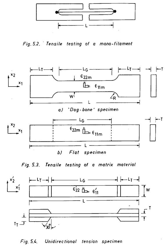
The tensile strength and Young's modulus of a high-modulus fibre is measured after mounting it on special slotted tabs and loading it at a constant strain rate (Fig. 5.2). The fibre strength Xf and the fibre modulus Ef are obtained from the load displacement plot.
![]() and
and ![]() (5.3)
(5.3)
where P,d and u are the load, fibre diameter and axial displacement, respectively.
5.2.4 Matrix Tensile Properties (ASTM D638-80)
A 'dog bone' specimen (Fig. 5.3a) is commonly used for a polymer
material, and the strength Xm corresponds to the ultimate failure
load. The Young's modulus Em and ultimate strain
![]() are measured using electrical resistance strain gauges
located at the centre of the specimen to determine νm. For thin
polymer sheets (in case it is not possible to make thick sheets), a flat
specimen (Fig. 5.3b) is recommended. The following relations are used:
are measured using electrical resistance strain gauges
located at the centre of the specimen to determine νm. For thin
polymer sheets (in case it is not possible to make thick sheets), a flat
specimen (Fig. 5.3b) is recommended. The following relations are used:
![]()
![]() and
and ![]() (5.4)
(5.4)
5.2.5 Tensile Properties of Unidirectional Lamina (ASTM D 3039-76)
High modulus and high strength fibrous composites cause special
problem of grip integrity. Wedge action frication grips are used to hold the
specimen. The materials for the tabs should have lower modulus of elasticity and
higher percentage of elongation. The tab thickness may range from 1.5 to 4 times
the specimen thickness. Typical specimen dimensions are presented in Fig. 5.4.
The longitudinal tensile properties ![]() as well as transverse tensile properties
as well as transverse tensile properties
![]() for a unidirectional lamina can be determined following this
test method. For longitudinal properties a 00 lamina with the width
W= 12.7mm is employed, and for transverse properties a 900 lamina
with W = 25.4mm is used. The specimens are loaded monotonically at a recommended
rate of 0.02 cm/min. The applied loads as well as longitudinal and transverse
strains are measured. The determinable characteristics are computed using
stress-strain plots and simple relations as given below:
for a unidirectional lamina can be determined following this
test method. For longitudinal properties a 00 lamina with the width
W= 12.7mm is employed, and for transverse properties a 900 lamina
with W = 25.4mm is used. The specimens are loaded monotonically at a recommended
rate of 0.02 cm/min. The applied loads as well as longitudinal and transverse
strains are measured. The determinable characteristics are computed using
stress-strain plots and simple relations as given below:
 For
00 specimen :
For
00 specimen : ![]()
For 900 specimen: ![]() /WT
/WT
5.2.6 Inplane Shear Properties (ASTM D 3518-82)
Several test methods, namely picture frame, rail shear (single and
double), tube torsion, plate twist and tension testing of an off-axis specimen,
were developed to determine the inplane shear properties of a unidirectional
lamina. All these methods require complex test specimens or special test
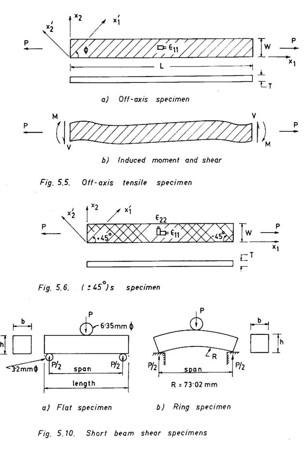
fixtures. The off-axis composite in which all fibres are oriented at an angle![]() , provides a simple specimen configuration (Fig. 5.5a).
, provides a simple specimen configuration (Fig. 5.5a).
The relation used to determine the inplane shear modulus is given by (see Eq. 6.41)
![]() (5.6)
(5.6)
from which G'12 is determined; as
![]() are known from the earlier test (Eq. 5.5) and E11
are known from the earlier test (Eq. 5.5) and E11
![]() is determined from the tensile test of an off-axis specimen.
However, the testing of an off-axis specimen requires greater care because of
coupling of normal stress and shear stress. The coupling introduces bending
moment and shear forces (Fig. 5.5b) at the ends where it is attached to the
grips. This in turn requires complex end fixtures to loosen the end fixity. The
other alternative is to test a long specimen so that the middle portion of the
specimen remains unaffected.
is determined from the tensile test of an off-axis specimen.
However, the testing of an off-axis specimen requires greater care because of
coupling of normal stress and shear stress. The coupling introduces bending
moment and shear forces (Fig. 5.5b) at the ends where it is attached to the
grips. This in turn requires complex end fixtures to loosen the end fixity. The
other alternative is to test a long specimen so that the middle portion of the
specimen remains unaffected.
ASTM D 3518-82 specifies a simple test method in which a ±450 symmetric laminate specimen (Fig. 5.6) is subjected to a tensile load. The specimen details (including end tabs details) are those given in ASTM 3039-76. The width W of the specimen is 12.7mm. The applied load and both longitudinal and transverse strains are continuously recorded till failure. The shear stress and shear strain are computed at the different levels of the applied load from the relations
![]() (5.6a)
(5.6a)
and the corresponding shear stress-strain curves are plotted.
The shear modulus and the shear strength are then obtained from
![]() (5.7)
(5.7)
5.2.7 Compressive Properties of Unidirectional Lamina (ASTM D3410-87)
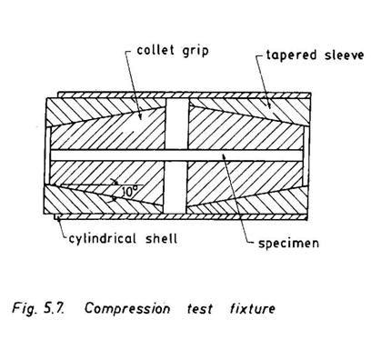
The premature failures, namely, fibre buckling, fibre breaking, matrix shearing, etc. are commonly encountered in a compression test. The main problem here is to ensure that the specimen failure is by compression. The specimen gauge length should be sufficiently short to restrict the failure mode to a truly compressive one. Besides the specimen ends are likely to get damaged due to want of close contact at all points between the end faces of the specimen and the platens of the testing machine during loading. Further, the specimen centerline should be perfectly aligned so as not to induce any eccentricity with respect to the load path. All these require an appropriate specimen configuration and a complex loading fixture.
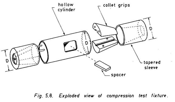
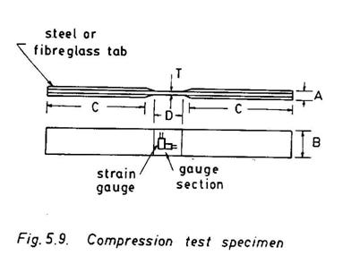
Three standard methods are currently available to determine the true compressive properties. The details of the testing procedure, specimen configuration, loading fixture, etc. are presented in ASTM D 3410-87. Of these the most commonly used method employs a Celanese test fixture (Figs. 5.7 and 5.8). The test fixture consists of truncated conical collet type friction grips contained in matching cylindrical end fittings (tapered sleeves). The colinearity of the end fittings is maintained by a hollow cylinder that houses all fittings. A central opening in the central part of the hollow cylinder provides an access to the gauge length of the specimen. A spacer is used to separate the grips and allow them to be closed with a preload, without preloading the specimen. The assembled fixture with specimen (Fig. 5.9) is loaded between the flat platens of the testing machine. The hollow cylinder, however, does not carry any load during the test. The recommended loading rate is 0.017 mm/mm/s.
The applied load P and strains (longitudinal and transverse) are measured at regular intervals. The compressive strength and longitudinal modulus, and Poisson's ratio for a longitudinal (00) specimen are computed from
![]() (5.8)
(5.8)
The properties for a transverse (900) specimen can also be determined in a similar way.
5.2.8 Interlaminar Shear Properties
The shear moduli G'13 and G'23, and
shear strengths X'13 and X'23 (Fig. 5.1) are normally
termed as interlaminar shear properties. There are no reliable methods for
determination of all interlaminar shear properties. ASTM D 2344-84 specifies the
determination of the interlaminar shear strength X'13 only. The
apparent shear strength determined using this method should be used only for
quality control and specifications purposes, but not as design criteria. Both
flat and ring short beam specimens (Fig. 5.10) can be used for which the span to
thickness ratio is 4 for most composites, except glass fibre composite when it
is 5. For the flat specimens, the corresponding length to thickness ratios are 6
and 7 so as to provide allowance for the support pins (3.2 mm
![]() ). The loading nose consists of a 6.35 mm
). The loading nose consists of a 6.35 mm![]() dowel pin. The recommended crosshead speed is 1.3 mm/min.
dowel pin. The recommended crosshead speed is 1.3 mm/min.
The apparent interlaminar shear strength is obtained using
![]() (5.9)
(5.9)
Acoustic Emission (AE) is essentially a technique of listening to a material. Whenever there is a change of condition in the material during loading and other service conditions, e.g., the initiation and propagation of a crack, sound waves (transient elastic waves) are generated by the rapid release of energy and propagate through the medium which contains that crack. These sound waves can be detected using an AE sensor glued to the surface of the medium at a convenient location. In the early fifties Joseph Kaiser, a German scientist, conducted experiments with metals and wood using sensitive electronic instruments and listened to the sound emitted by these materials during the process of deformation. He noted a phenomenon, termed as 'Kaiser Effect', that a material that had emitted AE signals during earlier stressing, would exhibit AE signals again when the previous stress was exceeded. Since Kaiser's first experimentation, there has been an all round growth in the use of AE techniques in materials and structures including composites.
AE sensors (piezoelectric transducers) are in principle high frequency microphones which first receive the sound waves and then convert them to electrical signals. These signals are very weak and therefore are amplified before they are passed to the signal conditioner where other electrical noises are filtered out. The filtered AE signals are then processed and analysed. A simple AE measurement system is schematically illustrated in Fig. 5.11. The electrical signals received by an AE sensor are processed by a wide variety of parameters : (i) count rate and total count of the number of signals which exceed a reference threshold, (ii) distribution of signal amplitude as a function of stress and time, (iii) energy of the detected signals and (iv) frequency content of the signals. AE can also be used to locate the crack or the signal source which emits AE signals. This requires the use of multiple transducers, and the source is located by the triangulation method, normally used to locate a seismic source. AE is an active NDT method and can be utilized for condition monitoring of composite parts and production control, as well as assessing severity of flaws and damages. It has been used extensively in composites not only to identify various failure modes, to define defects and to locate AE souces, but also to conduct real time monitoring during proof testing and in service. Each failure mode, namely, fibre breaking, matrix cracking, interfacial debond or delamination is found to exhibit distinct characteristic AE signals. But the identification of individual modes becomes extremely difficult when two or more failure modes occur simultaneously. The types of fibres and matrices, the anisotropy, the stacking sequence, structural boundaries, presence of micro-defects, etc. can considerably influence the AE signals and their propagation characteristics. All these problems need to be solved before AE can be routinely used as an NDT tool in development of composite materials and structures.
5.3.2 Holographic Interferometry
The holographic technique was discovered by Nobel Laureate Dennis Gabor in 1947, but it gained prominence after the discovery of the helium-neon laser in 1962. In holography, the entire optical wavefront both with respect to amplitude and phase is recorded in a film and phase is recorded in a film is called 'hologram' (after the Greek word holos meaning 'whole'). A hologram preserves the three-dimensional character of an object for which the hologram has been made. A simple holographic set-up (Fig.5.12a) mounted on a vibration isolated table, uses a laser, the light from which is split into two waves by a beam splitter. One wavefront i.e., the reference wavefront after being reflected from a mirror system reaches directly a holographic film. The other wavefront, i.e., the object wavefront reaches the film after being reflected from the object. The two wavefronts create a complex interference pattern which is recorded on the holographic film. The interference lines represent points with the same displacement. The coherence of the laser light permits the interference of these two waves, although there exist relatively large differences in path length. The recorded holographic film, or the hologram when illuminated with the reference wave, the object wave is reconstructed and a three-dimensional view of the object can be observed behind the hologram (Fig. 5.12b).
Several images which interfere with each other can be stored on the same film, which can be reconstructed when required. The holographic interferometry (HI) uses the technique of multiple exposure for application in NDT. The popular double exposure method, in which holograms of an object in two different states, e.g., stressed and unstressed, provide anomalies in the interference pattern which may in turn, reveal the existence of a flaw if any. The double exposure method is also known as frozen fringe HI. There are other HI methods which are used for specific purposes. The 'simulataneous method' or real time HI first creates a hologram of the object in a desired reference state, which is later used as a reference hologram with respect to which subsequent changes in the object position are recorded by filming the hologram image. The 'time averaging method' is used to record small amplitude oscillations of vibratory parts. The hologram of a vibrating body is first recorded on a film for a time interval longer than the period of oscillation and in the process a set of holograms are superimposed. The resulting hologram when reconstructed, reveals nodal lines as dark interference stripes.
HI has a great potential for NDT applications. The capability of HI is enhanced considerably after the introduction of video and popular with the NDT personnel working in the field of composites and composite structures. The real time monitoring of a component using HI, especially during the service life, still poses a problem as it is not easy to isolate vibration in the production and in-service environment. The vibrational displacement of the object as small as one-quarter wavelength of the laser light may produce fringes on the hologram. The use of phase-locked holography may alleviate problems associated the low frequency environmental vibration. The phase-locked holography uses the diffuse reflection of an unexpanded beam shone on a small portion of the test object as the reference beam. Another important development in this area is the electronic shearogrphy in which no separate reference beam is used. In this case, the returning object beam is doubly imaged with a video system. One image is then found to be slightly shifted or sheared relative to the original one. This shearing fringe pattern can be isolated from the real fringes.
X-ray radiography is the most commonly used NDT technique in industrial applications. X-rays are independent of the magnetic and electrical properties of a material and hence can be used with all materials. Two major characteristics of X-ray radiographic NDT method are that X-rays are absorbed differentially by different media and they produce photochemical effects in photographic emulsions. The intensity of a transmitted X-ray beam, when it passes through a medium, is given by
I = I0 e-µh (5.10)
where I is the intensity of the transmitted beam, I0 is the intensity of the incident beam, µ is the absorption coefficient of the medium and h is the thickness through which the beam travels. The absorption coefficient µ depends not only on the material, but also on the wavelength of X-rays.
Thus it is observed from Eq 5.10 that the X-ray beam attenuates when it passes through a material. The attenuation depends on the absorption coefficient and the thickness of the material. If there exists any defect, say, a void, in the material, the void (µ =0) does not absorb X-rays. So the intensities of the X-ray beams passing through the material thickness with and without a void will be different. When these transmitted beams are allowed to strike a photographic film, they create a contrast on the exposed film or radiograph (i.e., more the intensity, darker the film appears) from the knowledge of which the existence of a void can be predicted. It is also possible to determine the thickness and composition of a material by examining differences in the exposed film. Fig. 5.13 illustrates the principle how the radiograph is produced when a stepped specimen containing a hole is exposed to X-rays.
Normally voids of small sizes (closer to fibre dimensions), and cracks and delaminations that exist normal to the X-ray beam are not easily detectable. However, inclusions, cracks, delaminations and other material defects and damages that are aligned parallel to the X-ray beam can be readily revealed. The X-ray radiography has also been applied to investigate the microstructural details of damages using low energy X-rays as well as using an X-ray opaque penetrant (e.g., tetrabomo-ethane or zinc iodide). The penetrant, however, should not react chemically with the constituents of the composite medium. The development of radiography with microfocus (in which electrons are focused on a small area by means of a magnetic field) opens up new vistas for locating smaller details closer to fibre dimensions (10µm). Figure 5.14 shows the microfocal radiograph of a carbon composite panel with defects such as Teflon pieces, steel mesh, steel wire and steel balls. Microfocus radiography combined with real time image processing can be conveniently applied to investigate the nucleation and growth of cracks, delaminations and damages in composite and honeycomb structures.
A large portion of the attenuation of the X-ray beam, especially with low X-ray photon energies is due to Compton scattering. The X-ray backscatter imaging uses the process of recording and investigating scattered radiation from the object. The backscatter radiation provides quantitative information about variations in density due to presence of flaws, delaminations, etc. as well as change in materials. The method is found to be very useful for the inspection of laminated composite pressure vessels and motor cases, and very tight delaminations can be easily detected.
Computerized tomography (CT) provides a three-dimensional image of the desired section of an object and therefore all minute details of the variations in the image slice are recorded. The image is called a tomogram (after the Greek word tomos means 'to cut'). A point source of X-rays or gamma radiation is collimated to a flat, fan shaped beam which penetrates the slice of an object under inspection. The intensity of the transmitted beam is recorded by a detector. The movements of the beam and the recorder can be synchronized when the beam is rotated about the object along with the recorder and thereby a three-dimensional scanning of the whole slice is carried out. CT is now widely used in medical diagnostics and offers a great potential for uses in composite materials and structures.
Neutron radiography is another NDT technique which is finding applications in polymer composite structures. However, the major limitation of this method is that a transportable neutron source should be available at the site of inspection.
Thermography is also an effective NDT technique. It is basically a method of mapping and interpreting the contours of isotherms (equal temperature) over the surface of a body. A variation in the thermal field within the body occurs due to the presence of inhomogeneities, discontinuities and other defects which form hot or cold regions depending on their thermoelastic properties. These hot or cold regions exhibit sharp temperature gradients and can be located in the isothermal mapping. A thermal field within a body can be created externally by exposing it to a hot or cold source, or internally during the process of deformation when being loaded. A low level of mechanical vibration can raise the temperature in the regions containing discontinuities. A low temperature field may require spraying the body with liquid nitrogen. The thermal wave imaging technique employs a pulsed heat source to create pulsed thermal waves in the body. The thermal waves are then detected using acoustical or optical methods.
Thermal patterns or isotherms are usually recorded employing an infrared electronic camera (Fig.5.15). These are then related to inhomogeneities or defects. Thermography has been successfully used to detect delaminations and other types of flaws in composites. Figure 5.16 shows a thermal image of a blister between the peel ply and the subsurface on a 2mm thick CFRP panel. The image was acquired by heating the rear side of the panel using a hot air gun and focusing the infrared camera on the front side. Thermography should find extensive uses in metal-matrix composites, as metals are, in general, good thermal conductors. The real time thermography permits scanning and imaging a large surface area in a shorter period of time. The vibrothermography, in which mechanical vibrations are employed to induce thermal gradients near the damage regions, combined with the real time recording using an infrared video camera has been used to investigate damages in composites.
Ultrasonics is also a popular NDT technique for composites. The ultrasonic inspection in composites employs high frequency sound pulses usually in the megahertz range. Piezoelectric transducers are normally used to produce sound pulses. These sound pulses (ultrasonic signals) are allowed to propagate as a narrow beam through a material under examination. The sound waves attenuate based on the characteristics of the material (even if it is homogeneous) as given by the relation
![]() (5.11)
(5.11)
where
I is the intensity of the transmitted sound wave,
I0 is the original intensity of the sound wave,
α is the attenuation constant
and h is the distance travelled by the sound wave.
The intensity of propagating signals attenuates further due to the presence of inhomogeneities (e.g., different materials, poor adhesive bonding, etc.) and discontinuities (e.g., delaminations, cracks, voids, etc.) in the material. The sound signals are scattered and /or reflected at the interfaces of these defects. The characteristics of these defects are predicted by investigating the reflected and / or transmitted signals.
Fig. 5.17 illustrates how a reflected signal relates to the presence of a crack. In fact, more than 99% of an ultrasonic signal is reflected from a crack surface which is a material-air interface. This method of monitoring the reflected sound signal is called the 'pulse-echo' ultrasonic test. A piezoelectric transducer (probe) located at the top surface of a test specimen transmits a very short, high frequency pulse. The pulse is reflected from the crack top as well as from the bottom surface and is received by the same transducer (receiver). The variations in the amplitudes of reflected pulses when compared with that of the start pulse give the measure of attenuation. The depth at which the crack is located can be determined monitoring the time of arrival i.e., by relating the time axis with the sound path length. By mapping the surface and using angle probes the size and orientation of a crack can also be determined.
The main advantage of the pulse-echo method is that it requires access only from one side of a structure. The portable pulse-echo systems are very common in in-situ inspection. The pulse-echo system helps locating flaws at different depths. The pulse-echo C-scan can provide a map of all flaws located at different depths. The method is also very sensitive to foreign body inclusions. Even the existence of a piece of paper or a similar material contained within a laminate can be easily identified from the reflected signal strength.
The transmitted ultrasonic signals can also be monitored by placing a probe (receiver) on the bottom surface of the specimen. This is called the 'through-transmission' ultrasonic test. The presence of a flaw will reduce the intensity of transmitted signals. The through transmission ultrasonic technique is relatively more popular in composite applications. The method also permits ease of automation. A 'through transmission' ultrasonic C-scan provides complete information of the quality of an inspected part. Delaminations, inclusions and other defects normal to the ultrasonic beam are easily identified in the C-scan mapping. High frequency transducers (5 to 10 MHz) are employed to locate small defects or cracks parallel to the beam. Short focus transducers with 15 MHz are also being used in the ultrasonic C-scan system. High frequency transducers provide the sharper image of a defect and therefore help identification.
There are several other ultrasonic test techniques that are receiving sufficient attention in recent years. The 'ultrasonic polar backscatter' technique employs slightly angled beams. This helps detection of matrix cracking in oriented plies. The 'ultrasonic resonance' method makes use of the fact that the existence of a delamination reduces the normal surface stiffness of the material. A continuous ultrasonic wave is transmitted through the material, and the mechanical stiffness or impedance of the material is monitored. The reduced surface stiffness due to presence of a delamination decreases the surface loading on the ultrasonic probe and a shift in the phase, amplitude or resonant frequency is observed. The 'ultrasonic correlation' method enhances the sensitivity of ultrasonic signals (higher signal to noise ratio) by making use of a continuous wave cross-correlation technique. The method is very useful for highly attenuative composite materials. The 'acousto-ultrasonic or stress wave factor' test technique employs an ultrasonic transducer to send a simulated acoustic emission pulse through the test object. A defect or damage can modify the waveform which is monitored at a distance away from the source and is analysed. The 'ultrasonic microscopy' can image microstructural differences on the surface of a material. The reflection scanning acoustic microscope uses a very narrow high frequency (100 MHz to 1GHz) ultrasonic beam to scan the object line by line. Its limit of resolution is that of an optical microscope but the acoustic imaging, in some cases, provides additional information.
One of the major disadvantages of the ultrasonic NDT method is that a coupling agent is needed between the probe and the specimen to transmit and receive ultrasound signals. Normally either the specimen is immersed in a water bath or a water jet is directed to the specimen. Other coupling agents are also used. The coupling agents may have a deleterious effect on the specimen material. Further, this also poses special problems, when the size of a part to be inspected becomes large. The other alternative in such situations is to make use of transducers with dry coupling. The transducer is coupled acoustically to the specimen via a plastic material which is attached to the tip of the transducer. Typical CRT patterns from artificially embedded defects (paper and Teflon) in a carbon-carbon composite material are illustrated in Fig. 5.18.
Table 5.1 : ASTM standards for composite and related testing
|
ASTM D618-91 |
: |
Conditioning of Plastics and Electrical Insulating Materials for testing. |
|
ASTM D792-75 |
: |
Specific Gravity and Density of Plastics by Displacement. |
|
ASTM D 1505-75 |
: |
Density of Plastics by the Density Gradient Technique. |
|
ASTM D 3355-74 |
: |
Fibre Content of Unidirectional Fibre/Polymer Composites (Also see ASTM D3171-76 and ASTM D 3553-76) |
|
ASTM D 3379-75 |
: |
Tensile Strength and Young's Modulus for High Modulus Single Filament Materials. |
|
ASTM D2324-76 |
: |
Tensile Properties of Glass Fibre Strands, Yarns and Rovings used in Reinforced Plastics |
|
ASTM D 4018-81 |
: |
Tensile Properties of Continuous Filament Carbon and Graphite Yarns, Strands, Rovings and Tows. |
|
ASTM D 638-91 |
: |
Tensile Properties of Plastics |
|
ASTM D 695-91 |
: |
Compressive Properties of Plastics |
|
ASTM D 3039-89 |
: |
Tensile Properties of Oriented Fibre Composites. |
|
ASTM D 3552-77 |
: |
Tensile Properties of Fibre Reinforced Metal Matrix Composites. |
|
ASTM D 2291-80 |
: |
Fabrication of Ring Test Specimens for Glass Resin Composites. |
|
ASTM D 2290-92 |
: |
Apparent Tensile Strength of Ring or Tubular Plastics and Reinforced Plastics. |
|
ASTM D 790-91 |
: |
Flexural Properties of Plastics and Electrical Insulating Materials. |
|
ASTM D 3518-82 |
: |
Inplane Shear Stress-Strain Response of Unidirectional Reinforced Plastics. |
|
ASTM D 3918-80 |
: |
Definitions of Terms Relating to Reinforced Pultruded Products. |
|
ASTM D 4475-85 |
: |
Apparent Horizontal Shear Strength of Pultruded Reinforced Plastics Rods by Short Beam Method. |
|
ASTM D 3914-84 |
: |
In-plane Shear Strength of Pultruded Glass- Reinforced Pultruded Plastic Rods. |
|
ASTM D 3916-84 |
: |
Tensile & Properties of Pultruded Glass Fibre Reinforced Plastic Rod. |
|
ASTM D 3914-80 |
: |
Inplane Shear Strength of Pultruded Glass- Reinforced Plastic Rod. |
|
ASTM D 3410-87 |
: |
Compressive Properties of Unidirectional or Crossply Fibre-Resin Composites. |
|
ASTM D 2344-84 |
: |
Apparent Interlaminar Shear Strength of Parallel Fibre Composites by Short-Beam Method. |
|
ASTM D 3479-76 |
: |
Tension Fatigue of Oriented Fibre, Resin Matrix Composites. |
|
ASTM D 671-78 |
: |
Flexural Fatigue of Plastics by Constant Amplitude- of-Force. |
|
ASTM D 2585-90 |
: |
Preparation and Tension Testing of Filament Wound Pressure Vessels. |
|
ASTM D 2105-90 |
: |
Longitudinal Tensile Properties of Fibreglass Reinforced Thermosetting Plastic Pipe and Resin Tube. |
|
ASTM D 897-78 |
: |
Tensile Properties of Adhesive Bonds. |
|
ASTM D 3876-79 |
: |
Inplane Shear Strength of Reinforced Plastics |
|
ASTM D 3846-85 |
: |
Inplane Shear Strength of Reinforced Thermosetting Plastics. |
|
ASTM D 1623-78 |
: |
Tensile / Tensile Adhesive Properties of Rigid Cellular Plastics |
|
ASTM D 1621-79 |
: |
Compressive Properties of Rigid Cellular Plastics. |
|
ASTM D 747-90 |
: |
Apparent Bending Modulus (Stiffness) of Plastics by Cantilever Beam Method. |
|
ASTM D 696-91 |
: |
Coefficient of Linear Expansion. |
|
ASTM D 648-88 |
: |
Deflection Temperature of Plastics under Flexural Load. |
|
ASTM D 3917-88 |
: |
Dimensional Tolerance of Thermosetting Glass- Reinforced Plastic. |
|
ASTM D 543-87 |
: |
Resistance of Plastics (incluting Cast/Hot-moulded/ Cold-moulded Resinous/Sheet Products) to 50 Chemical Reagents. |
|
ASTM E 162-90 |
: |
Surface Flammability of Materials using a Radiant Heat Energy Source. |
|
ASTM D 2843-88 |
: |
Density of Smoke from the Burning or Decomposition of Plastics. |
1. Prepare a list of various properties (physical, thermal, electrical, chemical, mechanical, etc.) that are important in design and development of composite materials and structures.
2. How do you determine the tensile properties of fibres and matrices ?
3. Which properties of a unidirectional composite can be determined using tensile tests? Describe the methods.
4. Establish the theoretical basis of the formula defined in Eq. 5.9. Why the data obtained using this test method are not used for design purposes?
5. Derive the formulae used for determination of inplane shear properties of a unidirectional composite. Discuss the relevant test methods.
6. Compare the advantages and disadvantages of various NDT methods used in composite testing.
7. Which NDT methods will you recommend if you have to detect
i. A subsurface delamination
ii. An inclusion
iii. Distribution of voids
iv. A crack
v. Improper bonding
vi. Criticality of a flaw.
8. Describe the uses of ultrasonic methods in NDT of composites. Can these
techniques be used to determine composite moduli?