CHAPTER - 3
COMPOSITE MANUFACTURING
3.1 INTRODUCTION
3.2 MOULDING PROCESS FOR POLYMER MATRIX COMPOSITES
3.2.1 Matched-die Mould Methods
3.2.2 Contact Mould Methods
3.2.3 Filament Winding
3.2.4 Pultrusion
3.3 FABRICATION PROCESSES FOR METAL MATRIX COMPOSITES
3.3.1 Diffusion Bonding
3.3.2 Powder Metallurgy Process
3.3.3 Casting
3.4 FABRICATION PROCESS FOR CERAMIC MATRIX COMPOSITES
3.5 MACHINING
3.6 JOINING
3.7 BIBLIOGRAPHY
3.8 EXERCISES
Manufacturing is a very broad discipline and encompasses several processes such as fabrication, machining and joining. The fabrication methodology of a composite part depends mainly on three factors: (i) the characteristics of constituent matrices and reinforcements, (ii) the shapes, sizes and engineering details of products and (iii) end uses. The composite products are too many and cover a very wide domain of applications ranging from an engine valve, or a printed circuit board laminate, or a large-size boat hull or to an aircraft wing. The fabrication technique varies from one product to the other. The matrix types (i.e., whether they are plastics, metals or ceramics) play a dominant role in the selection of a fabrication process. Similar process cannot be adapted to fabricate an engine blade made with fibre reinforced plastics and metal matrix composites. The process parameters may also have to be modified, even when one uses the same matrix type, but two different matrices. For example, the processing with phenolics requires additional heating, whereas epoxies can be processed under ambient conditions. Particulate reinforcements and short fibres are mixed with resin to produce either bulk moulding composite compounds (BMCs) or sheet moulding composite compounds (SMCs) which are then used as base materials to fabricate composite parts. One method commonly used with BMCs is the injection moulding in which the BMC is heated and then injected into the mould cavity. On the other hand, the comparable moulding method used for woven fibre fabrics is the resin injection moulding. The process parameters like temperature, injcection pressure and curing time vary from one method to the other. Moreover, a composite car body panel, though highly curved and complex in shape may be compression moulded, while a spar stiffened helicopter rotor blade may have to be fabricated using filament winding and other moulding methods. Further, the accuracy and sophistication required to fabricate an aircraft composite wing section may not be necessary while fabricating a composite bridge deck or a silo. The main purpose of this chapter is to outline briefly the basic features of common composite fabrication methods. No attempt is made to elaborate the actual fabrication procedure of a particular composite component, as this is beyond the scope of the present book.
3.2 MOULDING PROCESS FOR POLYMER MATRIX COMPOSITES
Important moulding methods for fabrication of polymer matrix composite structural parts may be classified under matched die mould, contact mould (also called open mould), filament winding and pultrusion. There are two important stages in all moulding processes: laying and curing. The laying is the process in which moulding materials are laid on a mould in the mould cavity or on the mould surface that conforms to the shape of the part to be fabricated. The process of curing helps the resin to set, thereby providing the fabricated part a stable structural form.
The moulding materials are obviously reinforced plastics, either in the form of separate resin and reinforcements, or in the form of composites like bulk moulding compound (BMC), sheet moulding compound (SMC) or prepregs. These composite forms of moulding materials eliminate the mess of using wet resins during the lay-up process. A bulk moulding composite compound is prepared by mixing chopped strands or particulate reinforcements with a pre-mixed resin (normally polyester resin) paste. Fillers, thickeners, catalysts and other additives are also blended. The final mix is, either in the bulk form or extruded in the form of a rope and then stored for future use in the matched-die compression moulding process. A sheet moulding compound is, on the other hand, fabricated in the form of a sheet. Chopped strands or other particulate reinforcements are sandwiched between two layers of polyester resin pastes coated on two polyethylene carrier films. This resin-reinforcement-resin sandwich covered on two sides by the carrier films is thoroughly compacted by forcing it through a series of rollers and stored as rolls. Sometimes, continuous rovings are also added in between two resin layers to improve directional properties. Carrier films are removed prior to using them in moulds. BMCs and SMCs can be used in several moulding processes. The temperature, pressure and curing time of BMCs and SMCs are dependent on the type of the compound and the shape of the finished part. Prepregs are prepared by pre-impregnating fibre fabrics with resin. The system is only partially cured. The final cure takes place during the moulding process. Prepegs can be used in all important moulding processes. However, high quality products are realized, when curing is done in an autoclave. Prepegs yield superior products having all kinds of shapes with uniform resin content and consistent quality.
Several moulding techniques fall under the matched-die moulding method. The common feature in all these techniques is that the mould consists of two parts that form a cavity in between them. The shape of the cavity corresponds to that of the part to be moulded. The moulds are usually fabricated with cast iron, steel and aluminium alloy. Fibre reinforced plastics or wooden moulds are also used in some cold moulding processes. The mating surfaces of the moulds are first polished, cleaned and coated with a release agent. Next a gel coat is applied. The gel coat is a special resin that sticks to the surface of the moulded part during curing and provides it with an excellent surface finish. Pigments and other additives are also added to the gel coat resin for colouring as well as improving its resistance to wear, corrosion, heat, flame, weathering, etc. The gel coat is not provided, when the moulded part is to be adhesively bonded to another part, as the coat may not allow proper bonding. Both thermosetting and thermoplastic resins are used in the moulding materials. Thermoplastics in general and some thermosets in particular need process temperature higher than the ambient temperature. This is met by heating either the mould or the moulding. Venting ports are provided in the moulds for escape of excess resin and volatile matters.
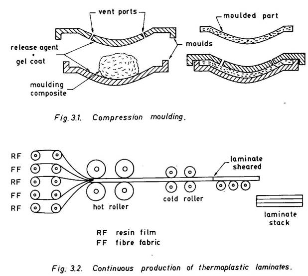
Compression moulding is the most commonly used matched-die moulding method. It is employed in fabrication of automobile body panels, housings for electrical appliances and machines, covers, sinks and several other parts. Typical moulds are shown in Fig. 3.1. The moulds can have a single cavity or multiple cavities with complex curved shapes. Provision may exist to heat either or both the moulds. The pressure is applied by mounting the moulds in a mechanical or hydraulic press or by some external means. The precise application of pressure and temperature and their duration and cycles can be controlled. The process can also be easily automated. On application of pressure and temperature, the mould material softens and then flows and fills the mould cavity. Further, continuation of heat and pressure accelerates curing. The dimensions close to those of the desired finished part can be obtained in compression moulding. This reduces, to a great extent, subsequent trimming and machining. The moulding material may be a
predetermined quantity of BMC, SMC, resin coated preforms/fabrics or prepregs. It is laid on the mould and then the moulds are closed. A barrier along the edge prevents the resin to flow out. The depth of the barrier also controls the thickness of the part. Heat and pressure are applied during curing. Once the curing is complete, the mould is opened and the part is removed.
Some resins like polyesters and epoxies are highly exothermic and may not require external input of heat during curing. The moulding material with these resins can be cold pressed. Cold press moulding is relatively less expensive and is suitable, when a part is smaller in size and simpler in shape (flat or slightly curved panels).
Cold stamping is also similar to compression moulding, but is normally used with thermoplastic sheets. The thermoplastic sheets are preheated, laid on the mould along with reinforcements and then cold pressed. An extension of this method to continuous production of fibre reinforced thermoplastic laminates is illustrated in Fig. 3.2. Alternate layers of fibre fabrics and thermoplastic films are fed through hot rollers that melt the resin and force it to penetrate and coat the individual fibres. The consolidated laminate is then passed through cold rollers which cure and harden the laminate.
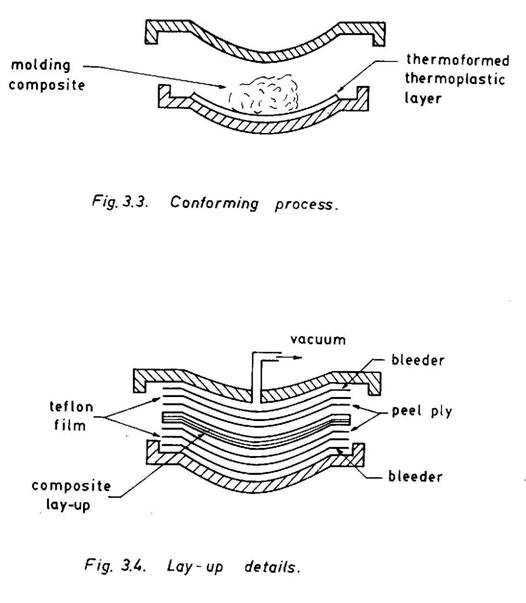
Conforming is also a matched-die moulding process specially developed to provide superior surface finish and durability to a composite part. A thermoformed thin thermoplastic layer is first placed on the mould (Fig. 3.3). The moulding composite material (BMC, SMC or resin-coated fabric) is then laid on the top of the thermoformed thermoplastic layer and hot pressed. The thermoplastic layer then sticks to the moulded part thereby providing it with a smooth surface having excellent properties. Various additives can be premixed in the thermoplastic layer to obtain desirable surface properties.
Press moulding is again similar to the compression moulding process, but it is used to make flat, slightly curved and corrugated laminates. For production of good quality laminates with uniform resin content, a perforated release film (e.g., Teflon film with perforations every 50 mm) and a bleeder (e.g., glass cloth, jute cloth or absorbent paper) are placed on both sides of the composite part (Fig. 3.4). In some applications, a peel ply (e.g., nylon cloth) is also used to achieve the required surface finish. On the application of pressure the excess resin is squeezed out and passes through the pores of nylon cloth and perforations of Teflon film and gets absorbed by the bleeder. The pressure is applied normally at the time of gelation to avoid excess loss of resin and to allow uniform resin distribution. The uniform flow of excess resin out of the moulding can be achieved by applying vacuum to one of the surfaces (here in Fig. 3.4 either the top or the bottom surface) of the mould cavity.
Injection moulding is a matched-die moulding process especially suitable for thermoplastic resin systems. Some thermosets can also be injection moulded. If the reinforcements are in the form of particles or very short fibres, they along with other additives, if any, can be premixed with resin. The mix is first heated in an injection chamber. The hot fluid mix is then forced into the closed mould cavity under high pressure and is allowed to cure. The cure part is removed after opening the mould. The method is suitable for fabrication of small to medium size parts such as valves, gears, instrument panels, etc.
If the reinforcements are in the form of preforms or fibre fabrics, they are laid in the mould cavity and the fluid resin is then injected into the mould cavity. The process is known as resin injection moulding. The injection pressure helps the resin to infiltrate through the fibre lay-up. A vacuum is also applied to the mould cavity to facilitate the penetration and even distribution of resin. For larger mouldings such as boat hulls, resin is injected at several locations. Also, cold cure resins of low viscosity and long gel time are preferred, as the injection time is longer in such applications.
In the reaction injection moulding, measured quantities of two liquid precursors such as a polyol and an isocyanate are mixed in a chamber and then injected into the hot mould cavity containing pre-laid reinforcements. Chopped strands and particulate reinforcements can also be blended with precursors prior to injection. The process is normally used for polymethane based systems and requires a relatively low injection pressure. It is highly suitable for mass production of composite parts.
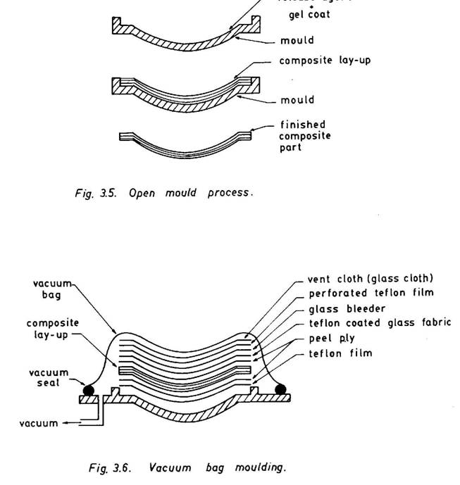
Contact mould methods are also known as open mould processes. In the open mould, there is only one mould (male or female) and as the name suggests the mould surface is open. A composite part is fabricated in contact with the open surface, and the shape of the open surface conforms to that of the moulded part (Fig. 3.5). The moulds are normally fabricated from cast iron, steel and aluminium alloy for application in hot processes, and fibre reinforced plastics and wood for cold processes. The mould surface is cleaned and polished prior to moulding and is filled up with coating of a release agent and a gel. The moulding materials are normally resin-coated woven rovings and fabrics, chopped strand mats and prepregs. These are laid on the mould by either the hand lay-up process or the spray-up process. In the hand lay-up process woven rovings, fabrics and/or chopped strand mats are placed layerwise on the release agent and gel coated mould surface. After laying of each layer, it is coated with resin using a brush or a spray gun. Some time gap is allowed for the applied resin coat to gel, before laying the next layer and applying resin to it. Squeegees or rollers are used for uniform distribution of resin and consolidation for the laminate. In the spray-up process, chopped strands or particulate reinforcements and the resin are sprayed separately to the mould surface. In some applications, continuous fibre strands are fed to a combined chopper and spray gun system by which chopped fibres and resin are sprayed simultaneously to the mould. After completion of the laying up process, the moulding is allowed to cure. Curing is done either at room temperature conditions or by heating the mould assembly in an oven. In the case of prepregs the hand lay-up process is employed. However prepregs do not require additional resin coating.
For compact and voidless finished products of higher mechanical properties, other improved moulding processes such as vacuum bag moulding, pressure bag moulding processes such as vacuum bag moulding, pressure bag moulding and autoclave moulding are preferred. An improved open mould set-up with pre-curing lay-up details that are generally employed in a vacuum bag moulding, is shown in Fig. 3.6. The whole moulding system is covered with a flexible vacuum bagging film made of nylon or neoprene rubber. The edge of the bag is sealed using vacuum sealing compounds. Layers
of vent cloth, perforated Teflon film, fiberglass bleeders, Teflon coated fiberglass fabrics and nylon peel ply, in that order, are kept between the vacuum bag and the composite lay-up. When vacuum is applied, these materials allow attainment of uniform vacuum throughout and provides path for escape of volatiles, trapped air and excess resin from the composite lay-up. The vacuum also induces uniform atmospheric pressure on the top surface of the mould assembly and thereby helps in uniform distribution of resin and futher consolidation of the laminate. It also provides better finished surfaces. The whole assembly can be put in an oven or an external heating arrangement can be made, if a high temperature curing is needed.
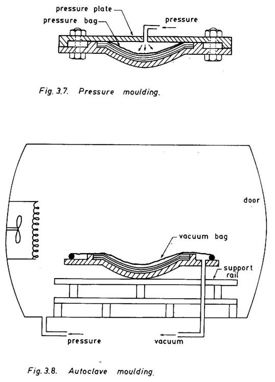
In the case of pressure moulding, the vacuum bag is replaced by a pressure bag and the whole system is covered by a pressure plate (Fig. 3.7). The required pressure is then applied through an inlet pipe located at the cover plate. In this method, it is possible to apply pressure higher than one atmosphere. The higher pressure ensures proper consolidation and densification of the composite lay-up. However, the method cannot be applied to a male mould.
Autoclave moulding is a highly sophisticated process in which controlled temperature and pressure can be applied. In addition, vacuum is also applied to suck volatile matters and entrapped air or gases. The whole assembly as shown in Fig. 3.6 is put inside an autoclave (Fig. 3.8) which is a pressurized cylindrical hot chamber. Curing takes place in presence of simultaneous pressure and temperature. After curing, the mould is taken out of the autoclave and the cured composite is laid with prepregs, as it permits controlled variation of prescribed temperature and pressure with respect to time. It yields highly densified and voidless quality products and is therefore greatly favoured in fabrication of all major aerospace components like aircraft wing parts, control surfaces, helicopter blades, filament wound rocket cases, pressure bottles, etc.
The filament winding process is employed for fabrication of a continuous fibre reinforced composite structure having an axis of revolution. Common examples of such structures are tubes, pipes, cylindrical tanks, pressure vessels, rocket motor cases, etc. Continuous fibre strands or rovings are first coated with resin in a resin bath and then fed through rollers to squeeze out excess resin and finally wound, under constant tension, around a collapsible mandrel. The outer diameter of the mandrel corresponds to the inner diameter of the part to be fabricated. The mandrel is usually made of steel. However, other materials like plastic foam and rubber are also used in fabrication of some mandrels. A steel mandrel can be so designed that it can be dismantled mechanically and removed part by part without damaging the filament wound composite part. Some foam mandrels can be chemically dissolved. An inflated rubber mandrel can be collapsed by deflating it. The mandrel is positioned, either horizontally (for helical winding) or vertically (for polar winding), on a carriage that moved back and forth along the direction parallel to the rotational axis. In addition to the translational (axial) motion induced by the carriage, the mandrel can also rotate about its own axis. Both rotational and axial motions of the mandrel can be properly controlled either manually or using an automatic system. The rotation of the mandrel about its axis of revolution facilitates winding of filaments on the outer surface of the mandrel.
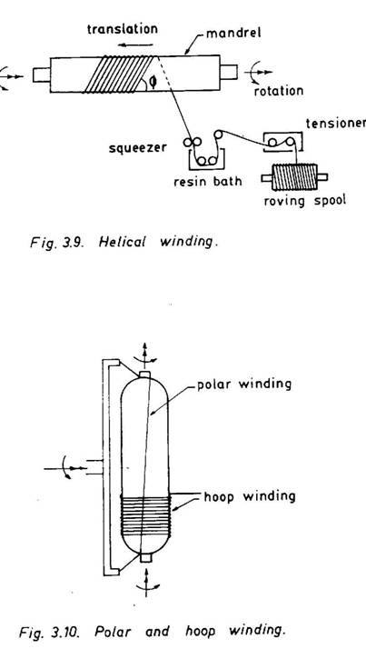
There are basically two types of filament winding patterns: helical winding and biaxial winding. In the helical winding (Fig. 3.9) a constant angle Ø (known as helical angle) is maintained by controlling the rotational and axial motions of the mandrel. By reversing both axial and rotational motions, the filaments are wound with a minus helical angle, -Ø. Structural components having circular cylindrical shapes like tubes, pipes and
cylinders are normally fabricated with alternating helical angle +Ø and –Ø. When the filaments are wound at an angle Ø = 900, the winding is called hoop winding. Similarly, when Ø=0, it is termed as axial winding. In the biaxial winding pattern, there may exist a combination of either hoop winding and axial winding pattern commonly employed for filament winding of circular cylindrical closed end vessels (with or without small end openings), such as motor cases and pressure tanks, is known as polar winding or polar wrap (Fig.3.10). A combination of both polar and hoop winding is normally provided for proper strengthening in the circumferential direction. After winding is complete, the mandrel is removed from the carriage and placed in an oven, if required, for curing. Filament wound products for aerospace applications are normally cured in an autoclave. For such curing, vacuum bagging as described earlier, of the mandrel assembly has to be carried out before placing it in an autoclave. After curing, the mandrel is dismantled and the finished part is removed. Filament winding yields a component with a high degree of fibre volume fraction. Prepreg tapes can also be wound in similar ways.
Filament winding can also be used, when the shape of the part is not a shell of revolution. The winding is first carried out on an inflated mandrel made of rubber. The mandrel is deflated, once winding is complete. The deflated filament wound component is placed in a closed match-die mould and the mandrel is inflated again to apply pressure from inside. The mould is simultaneously heated to facilitate curing. The cured finished part has the outer shape same as the inner shape of the mould. Several non-circular sections (e.g., box section and airfoil sections) can be fabricated using this technique.
Braiding is another form of filament winding process and is employed in fabrication of bars, tubes, bends, etc. with both circular and non-circular hollow sections. It is carried out on an axially moving mandrel which is positioned through the central hole of a rotating ring. A number of spools containing continuous rovings are mounted on the ring. The fibres are pulled out from these spools and wound around the moving mandrel creating an inter-woven winding pattern which provides high interlaminar properties.
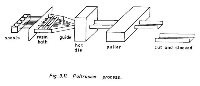
Pultusion, to some extent, is analogous to the metal extrusion process. In the pultrusion process continuous fibre reinforced structural sections can be produced by pulling the resin-coated filaments through a die unlike in the metal extrusion process, where hot metallic rods, bars and flats are pushed through a die to produce extruded parts. The pultrusion process is schematically shown in Fig. 3.11. Continuous fibre strands taken from a number of spools are sequentially pulled through a resin bath, a shaping guide and a hot die (or a cold die and an oven). The fibres are coated in the resin bath and the excess resin is squeezed out. The shaping guide provides a gradual change
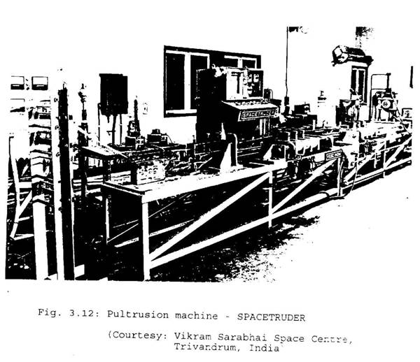
from a simpler to a more complex pre-formed shape close to that of the pultruded part. For example, to obtain a pultruded channel section, a flat form with no flanges is gradually changed to a channel section of desired dimensions. The final shape is realized when the preformed shape is pulled through a hot die and gets cured. Continuous strand mats and woven fabrics can also be pulled along with filament strands to provide better transverse properties to the pultruded sections. The die is a very critical component in the fabrication process. It is usually made of chromium plated steel and should have a highly smooth surface. A smooth surface inhibits sticking of the resin at the entry segment, where only the gelation of resin, but not curing has been initiated. Thermosets like epoxies and polyesters are normally used in the pultrusion process. Phenolics can also be used, but have to be preheated. Experimentation with thermoplastics has also been carried out. Pultrusion is a continuous process and therefore provides scope for automation. A pultursion machine “SPACETRUDER”, designed and developed at Vikram Sarabhai Space Centre, Trivandrum, India is shown in Fig. 3.12. It can produce continuous lengths of FRP sections such as rounds, square bars, channels, angles, etc. using glass, carbon or aramid fibres and epoxy or polyester resins.
3.3 FABRICATION PROCESSES FOR METAL MATRIX COMPOSITES
Aluminium, magnesium, titanium and nickel alloys are commonly used as metal matrices, although several other matrix materials including super alloys have also been used. Both metal and ceramic reinforcements are employed. The choice of a particular matrix-reinforcement system is mainly controlled by the end use of the fabricated composite part. Several parameters influence the selection of a particular fabrication process. These are (i) types of matrices and reinforcements, (ii) the shape, size, orientation and distribution of reinforcements, (iii) the chemical, thermal and mechanical properties of reinforcements and matrices, (iv) shape, size and dimensional tolerances of the part and (v) finally the end use and cost-effectiveness. Compared to standard metallurgical processes, fabrication methods for metal matrix composites are much more complex and diverse. Some problems that are of major concern are the densification of the matrix while maintaining its purity, the control of reinforcement spacing and proper chemical bonding between the matrix and reinforcements. Based on the physical state of the matrix i.e., solid phase and liquid phase, fabrication processes can be grouped under solid phase processing and liquid phase processing. In the solid phase processing, the matrix is in the form of sheet, foil or powder. The diffusion bonding and power metallurgy processes are the two major solid phase processing techniques, while casting (also known as liquid metal infiltration) processes are related to liquid phase processing. Solid phase processing has certain advantages over liquid phase processing. The processing temperatures are lower, diffusion rates are slower and the reaction between reinforcements and the matrix is less severe. Secondary processes like forging, rolling, extrusion and superplastic forming are also important, as much care is needed to reduce damage to reinforcements.
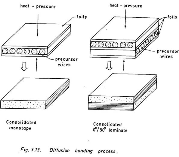
The diffusion bonding employs the matrix in the solid phase, in the form of sheet or foil. Composite laminates are produced by consolidating alternate layers of precursor wires or fibre mats and metal matrix sheets or foils under temperature and pressure (Fig.3.13). The precursor wires are collimated filaments held together with a fugitive organic binder. This is achieved either by winding binder-coated filaments onto a circular cylindrical mandrel or by spraying the binder on the filaments that are already wound on a mandrel. When the solvent is evaporated, the fibre-resin combination forms a rolled fibre mat on the mandrel surface. The binder resin in precursor wires and fibre mats decomposes at a high temperature without leaving any residue. Under temperature and pressure metal sheets or foils melt and diffuse through fibre layers to form a laminate. A multilayered laminate may have any desired stacking sequence. A monotape (i.e., a unidirectional lamina) in which a precursor layer or a fibre mat is sandwiched between two metal sheets or foils, forms the basic building block. Several complex composite components can be fabricated by stacking monotapes as per design requirements. The temperature, pressure and their duration are very critical for making good quality composites. Carbon fibres have been successfully combined with matrices like aluminium, magnesium, copper, tin, lead and silver to make a wide range of carbon fibre reinforced metal composites. A number of products ranging from flat plates to curved engine blades have been fabricated using the diffusion bonding technique. One interesting example is the 3.6m long high gain antenna boom that acted as a wave guide for the Hubble space telescope. The boom is made with diffusion bonded carbon fibre reinforced aluminium (AA 6061) composite and is of tubular cross-section with internal dimensional tolerances of ±0.15 mm. Several other composites, for example, boron, beryllium and steel fibres in aluminium alloy matrix have been manufactured using the diffusion bonding process. Large composite sheets can be produced by employing the vacuum hot rolling technique.
3.3.2 Powder Metallurgy Process
Almost all metals and their alloys can be converted into powder form. Metal powders are commonly produced by atomization techniques. A stream of molten metal is disrupted either by impacting another fluid (gas or water) jet under high pressure or by applying mechanical forces and electrical fields leading to formation of fine liquid metal droplets which then solidify resulting in fine powder particles. The inert gases, argon and nitrogen, are used in the gas atomization, and the resulting powder particles are smooth and spherical with 50-100µm diameter. The impact of very high intensity gas pulse waves in supersonic and ultrasonic gas atomization can lower particle sizes to 10µm. The water jet impact produces irregular particles (75-200 µm diameter). Both gas and water contaminate particles with oxygen. In another method, known as vacuum atomization, the liquid metal supersaturated with gas under pressure is suddenly allowed to expand in vacuum causing the liquid to atomise and produce spherical powders with diameters ranging between 40-150µm. In the rotating electrode technique, a prealloyed electrode is rotated at a high speed (about 250 rps) while it is melted by an arc or plasma beam. Spherical droplets of the molten material are ejected centrifugally and, on being cooled in an inert environment, produce high quality, spherical powders with 150-200µm diameter. The centrifugal atomization process combined with rapid solidification yields spherical powders less than 100µm diameter. Both the electrohydrodynamic atomization in which an electrical field is applied on the surface of a liquid metal to emit droplets and the spark erosion technique, where repetitive spark discharge between two electrodes immersed in a dielectric fluid produces metal vapour, thereby yielding very fine powders with diameter as low as 0.5 µm or less.
Powder metallurgy is a versatile process but its application to fabrication of metal matrix composites may not be straight-forward, especially because of the presence of reinforcement phase.
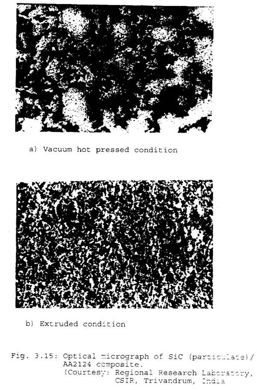
There are quite a few composite fabrication techniques using continuous fibres of which two processes that use hot pressure bonding need special mention. In one process (known as powder cloth process), metal powder filled clothes are first produced by mixing metal matrix powders with an organic binder and then blending with a high purity Stoddard solution. On application of low heat, the Stoddard solution evaporates leaving behind a dough-like mixture which, on rolling, yields a metal powder cloth. Alternate layers of powder clothes and fibre mats, when hot press bonded, form a composite laminate (Fig.3.14). The binders usually burn out without leaving any residue. When the reinforcements are in the form of short fibres and particulates, metal matrix powder and reinforcements are thoroughly blended, and the blend is degassed to remove volatiles and then a composite ingot is formed by either hot pressing in vacuum or hot isostatic pressing. The composite ingot is subsequently used to fabricate structural components using secondary fabrication processes. Major problems are encountered in controlling the shape, size and distribution of reinforcements in the matrix. The alignment of short fibres, elongation of particulates i.e., a sphere changing to an oblate or nonspherical shape, and uniform dispersion or clustering are the common occurrences that influence the microstructure of the composite. Figure 3.15 shows an optical micrograph of SiC particulate (30% by volume)/AA2124 composite a) in the vacuum hot pressed condition showing the necklace structure of particulate reinforcement around the matrix particles and b) in the as extruded condition showing the elimination of necklace structure and improved distribution.
In the thermal spray processes, metal powders, are deposited on the fibre substrates using either plasma spray or arc spray techniques and composites are subsequently produced by consolidating these metal matrix coated fibres under heat and pressure. The plasma spray technique is employed to deposit spherical metal powders that are injected in the plasma stream (the temperature is about 10,000K and the traveling speed is around Mach 3) within the throat of the gun. The powder particle size is very critical, because the powder should melt, but not vapourise before it reaches the substrate. The arc spray technique uses continuous metal matrix wires of 0.16-0.32 cm diameter instead of metal powders. Two wires of opposite charge are fed through an arc spray gun. The electric arc produced between the wire tips causes the tips to melt. An argon gas stream that passes through the gun and between the wires, carries with it droplets of molten metal and deposit them on the fibre substrates. Both plasma spray and arc spray techniques have been used to produce composite monotapes by winding continuous fibres on a mandrel and then spraying metal matrix powders on them. These monotapes are subsequently used to fabricate structural components using the diffusion bonding process.
The powder metallurgy process has been used to produce composites such as boron, carbon and borsic fibres with aluminium alloy, SiC fibres with cromium alloys, boron and Al2O3 fibres with titanium alloy, tungsten and molybdenum fibres with nickel alloy and several other composite systems.
Casting or liquid infiltration is the process in which molten matrix is infilatrated into a stack of continuous fibre reinforcements or discontinuous reinforcements (short fibres and particulates) and is then allowed to solidify between the inter-reinforcement spaces. In the case of discontinuous reinforcements, they can also be pre-mixed with molten matrices prior to casting, using techniques such as mechanical agitation, mixing by injection with an injection gun, centrifugal dispersion and dispersion of pellets (formed by compressing the metal matrix and reinforcements) in a mildly agitated melt. This pre-mix or the composite slurry is used for subsequent casting. There are several casting methods that can be used to produce metal matrix composite components. Some important casting methods are sand and die castings, pressure die castings, centrifugal casting, squeeze casting and investment casting.
In the sand and die casting process, the preferential concentration of discontinuous reinforcements, either at the top or at the bottom depending on their densities lower or higher than the metal matrices, takes place in view of the slow cooling rate of sand moulds. A more uniform dispersion or dispersoids can be achieved by agitating the mix, cooling the mould or employing a metal mould. The pressure die casting produces relatively void free composites and permits fabrication of large-size parts with intricate shapes. In the centrifugal casting, solidification takes place in a rotating mould. In this process, the centrifugal acceleration forces the heavier discontinuous reinforcements to concentrate near the outer periphery and the lighter ones lie closer to the axis of rotation. Squeeze casting (also known as liquid forging) is the process in which the molten matrix is infiltrated, under high pressure, onto a preheated stack of discontinuous reinforcements or fibre performs laid on a metal die. Solidification takes place also under pressure. Several critical components have been developed using squeeze casting. The Toyota piston, made of ceramic fibre and aluminium matrix, is one such example. In the investment casting, continuous fibre reinforcements are laid using usual filament winding or prepreg laying procedures. Composites are then produced by infiltrating the lay-up with a molten matrix under pressure or vacuum.
Casting is the most commonly used process for manufacture of metal matrix composites. Figure 3.16 exhibits a graphite/aluminium composite ingot and its composite products.
3.4 FABRICATION PROCESS FOR CERAMIC MATRIX COMPOSITES
Ceramic such as glass, glass-ceramics, borides, carbides, graphite, nitrides and silicates reinforced with both metallic and ceramic particles, whiskers and fibres provide enhanced strength and toughness even at high temperatures. Some ceramic composites, especially, carbon-carbon composites exhibit remarkable strength properties at a temperature as high as 20000C or more. The fabrication processes for ceramic matrix composites are, in many ways, similar to those for metal matrix composites. As in the powder metallurgy processes for MMCs, short fibres and particulate reinforcements are mixed with ceramic powders and then hot pressed to produce CMC products. Common dispersion particles are SiC, TiC, BN and ZrO2. SiC whiskers are very commonly used to reinforce matrices such as glass, ZrO2, B4C, Al2O3, cordierite, Si3N4 and several other ceramics. They are rod or needle shaped single crystal short fibres with diameter ranging from 0.1-5.0 µm and length 5-200 µm. SiC whiskers which apparently look like powders and ceramic powders are thoroughly mixed and then hot pressed to make composite. The proper mixing of SiC whiskers and ceramic powders is critical to produce composites with desirable properties. This is usually carried out using high shear mixing, ultrasonic dispersion, milling and several other mixing methods. The cutting tools for high nickel alloys employ SiC whisker reinforced alumina. They provide cutting rates up to ten times higher than conventional tools. Due to excellent wear resistance of SiC whisker reinforced composites at high temperatures, these materials find wide uses in dies for metal extrusion, heat engine valves, grit blast nozzles and other high temperature applications. The plasma spray techniques, as employed in metal matrix composites, has also been used in ceramic composites.
Hot pressing and sintering of ceramic materials normally require high temperature and pressure at which reinforcements degrade due to chemical reactions on the reinforcement-matrix interface. A number of glass systems such as lithium aluminosilicate (LAS), magnesium aluminosilicate (MAS), barium magnesium aluminosilicate (BMAS), etc. have been hot pressed at relatively lower temperature without causing any damage to the reinforcement. Transfer moulding and injection moulding techniques have also been successfully carried out using glass systems.
Infiltration of molten ceramics is also a common fabrication process for ceramic matrix composites. The high melting points of ceramics, however, may degrade the reinforcements. One way to circumvent this problem is to use polymer precursors that bring down the process temperature. However, during the conversion of a polymer precursor to the ceramic matrix, a lot of volatile matters escape causing shrinkage of the matrix. The matrix also becomes porous. The porosity can be reduced to a large extent by reimpregnation. Several precursor polymers have been studied to produce SiC and Si3N4 matrices. In the sol-gel technique, gels are used to aid uniform infiltration of matrices. For example, tetrafunctional alkoxides are employed to infiltrate oxide matrices. This reduces the fibre damage to some extent due to lower viscosity of the gel-mixed slurry, but the shrinkage problem remains.
Reaction sintering (also known as reaction bonding or reaction forming) eliminates some of the problems associated with hot press sintering and liquid infiltration, such as fibre damage, matrix shrinkage, porosity, etc. In this process, ceramic matrices are reaction formed. A typical example is the Si3N4 matrix, which is reaction formed by nitriding Si powder. The SiC matrix has also been successfully reaction bonded. The reaction sintering process seems to have great potential, although the process is not yet fully developed. The main drawback is that the resulting composite may have excessive porosity.
In the chemical vapour deposition process (more often called as chemical vapour infiltration), a ceramic matrix is chemically vapour deposited on the surfaces within a fibre preform. The preform is kept in a high temperature furnace (reactor). A carrier gas (H2, Ar, He, etc.) stream passes through a vessel containing gaseous reagents and carries their vapour into the reactor. In the reactor, the chemical reaction of gaseous reagents leads to the formation and deposition of ceramic matrix vapour on the heated surface of the preform. Other reaction powders diffuse out of the preform and are carried by the flowing gas stream out of the furnace. The deposition process continues, until all the inter fibre spaces are filled up resulting in a homogeneous and more or less void free composite. The main advantage of this process is that it causes minimum damage to the fibres, as the process temperatures and pressures are relatively lower compared to those in hot press sintering and liquid infiltration. Also this process permits fabrication of composite parts with irregular shapes. The deposition reaction may be of reduction, thermal decomposition or displacement type. A typical reaction such as
CH3 Si Cl3 ® SiC + 3 HCL
is responsible for deposition of SiC vapour. The reagents and vapour deposition temperatures for a few ceramic matrices are listed in Table 3.1. Plasma has also been used to assist chemical vapour deposition, for example, as in the case of SiO2 matrix.
The deposition process is carried out under any of these conditions: (i) maintaining a uniform temperature through out the preform i.e., isothermal condition, (ii) providing a thermal gradient through the thickness of the preform, (iii) isothermal, but forcing the flow of reactant gases into the preform, (iv) both with thermal gradient and forced flow and (v) with pulsed flow, i.e., cyclic evacuation and filling of the reactor chamber with reactants.
Carbon-carbon composites are fabricated by either resin impregnation and subsequent carbonization or chemical deposition of carbon vapour. The latter process has
Table 3.1: Typical ceramic matrices, reagents and vapour deposition temperatures
|
Ceramic Matrix |
Reagents |
Deposition temperature, oC |
|
ZrB2 |
ZrCl4, BCl3, H2 |
1000-1500 |
|
HfB2 |
HfCl4, BCl3, H2 |
1000-1600 |
|
TiC |
TiCl4, CH4, H2 |
900-1600 |
|
SiC |
CH3 SiCl3, H2 |
1000-1600 |
|
B4C |
BCl3, CH4, H2 |
1200-1400 |
|
Si3N4 |
SiCl4, NH3, H2 |
1000-1550 |
|
BN |
BCl3, NH3, H2 |
1000-1300 |
|
Al2O3 |
AlCl3, CO2, H2 |
500-1100 |
|
Cr2O3 |
Cr (CO)6, O2 |
400-600 |
|
SiO2 |
SiH4, CO2, H2 |
200-600 * |
|
Y2O3 |
YCl3, CO2, H2 |
1200 |
|
ZrO2 |
ZrCl4, CO2, H2 |
800-1200 |
|
TiSi2 |
TiCl4, SiCl4, H2 |
1400 |
|
C |
CH4 |
900-2250 |
* plasma assisted
been found to yield superior carbon-carbon composites and has been used to produce aerospace components such as aircraft brake discs and engine exit nozzles, nose cones, rotors, combusters, etc. A hydrocarbon reagent, e.g., CH4 may be used along with hydrogen, nitrogen or any inert gas for chemical deposition of carbon vapour on a carbon fibre substrate (perform).
Machining is an important stage of the overall manufacturing process. It helps to realize finished products with specified dimensions, surface finish and tolerances. Conventional machining processes require direct contact between the cutting tool and the part to be machined. The quality of the machined part and the tool wear are two major concerns in these machining processes. The performance and integrity of the machined part depend primarily on the quality of machining. The removal of material in a metallic alloy is based on a shear process. The material removal in a composite may be totally different from that in metals and their alloys. The application of conventional metal cutting tools in composites leads to flaws such as fibre damage, delamination and cracking which are not encountered in metal cutting. The presence of these defects and tool wear has been observed while applying the machining processes such as shearing, abrasive cutting, grinding, profiling, punching and drilling on fibre reinforced composites. Even the use of high speed drilling has not been found to be very much effective in reducing the fibre damage or tool wear. Tool wear has always been a major problem in machining composite parts. It depends on the feed rate, cutting speed, cutting direction, temperature, and relative hardness properties of the tool material and the composite part to be machined as well as several other parameters. The highest tool wear is observed for a particular combination of feed rate and cutting speed. The tool wear rate is found to be inversely proportional to the hardness of the tool, when the tool is harder than the composite to be machined. Diamond tools normally exhibit a longer tool life. Tungsten-carbide tools and silicon-carbide grinding wheels are also useful. It is difficult to machine boron fibre composites because of extreme hardness of boron fibres. Some special problems arise during machining of aramid fibres. These can be tackled using specially designed tools which are commercially available.
There are several non-conventional machining methods which avoid direct contact between the machine and the work piece, thereby eliminating the problem of tool wear and improving the quality of the machined component. A narrow laser beam of 0.1 mm diameter or less with a power in excess of 108 W/cm2 can be directed to cut various composite materials. The CO2 laser system with 10.6 µm wavelength has been successfully used to machine fibre reinforced polymer composites. A ND:YAG (neodymium/yttriumaluminium-garnet) laser system with wavelength of 1.06µm and 200 pulses per second, can be used to cut metal composites. The water jet cutting process employs a jet cutting nozzle of 0.13 mm diameter and water pressure in excess of 350 MPa. In the abrasive water jet process, abrasive particles are added to the jet stream to facilitate the cutting process. Both these water jet methods are used in cutting both metallic and non-metallic composites. The electrical discharge machining process is based on erosion caused by an electrical spark developed between an electrode and the part to be machined in the presence of a dielectric fluid and has been effectively used to machine composite parts which are electrically conductive. Other non-conventional machining processes such as electrochemical machining, electron beam machining and ultrasonic machining also have good potential in composite applications. One of the primary disadvantage with all these non-conventional machining processes is that it may not be possible to induce shape changes, as is done by conventional processes. However, these unconventional processes, in most cases, lead to high quality cuts with minimum fibre damage, delamination and cracking as well as excellent surface finish.
A joint is an essential element in a structural system. However, it is the weakest link, and therefore the selection of a particular type of joint, its fabrication and/or assembly need careful consideration. There are two basic types of joints, bonded and mechanically fastened, which are also applicable to all composite systems. Bonded joints are preferred, because of their efficient load transfer which is primarily through shear in the bond layer. The bond shear stress as well as direct or induced peel stresses can be controlled by configuring and designing the joint properly. Some of the common bonded joint configurations are illustrated in Fig. 3.17. The mechanically fastened joints (bolted, riveted, etc.), on the other hand, are relatively inefficient because of high stress concentrations around bolt holes. The process of load transfer in a mechanically fastened joint, especially involving deformable bolts or pins and composites, is very complex. The modes of failure in a typical single-pin bolt joint are shown in Fig.3.18. The residual strength of such a joint is quite low and is usually less than a half of the composite laminate strength. However, mechanical fastening is a practical necessity in view of ease of repeated dismantling and assembly as well as repairability.
Bonded joints are again of two types – adhesive bonded and fusion bonded or welded. An adhesive bonded joint normally involves application of an adhesive layer on the overlapping surfaces of the adherends. The adhesive layer is usually a thermosetting resin. The bonded joints are, therefore, highly effective for composites with thermosetting resins. They are also good for metal and even ceramic joints, provided they are not exposed to temperatures higher than the tolerable limit of the adhesive. The surface treatment of adherends, prior to the application of the adhesice layer, is necessary to achieve better adhesion properties. But the thermosetting adhesive layer is not compatible with thermoplastic composites. Thermoplastic composite adherends need to be fusion bonded. In fusion bonding no new material is added. The process involves surface preparation, heating and melting of the bond surfaces, pressing for intermolecular diffusion and entanglement of the polymer chains and cooling for solidification. The bond surfaces are treated mechanically and/or chemically to remove all contaminations including loose particles, dirt, release agent, oil, etc. The heating and melting are carried out using any of the welding techniques employed in plastics. In the hot-plate welding process, the surfaces to be bonded are heated by making contact with a hot plate. The hot gas welding normally employs a hot gas. In the case of a butt joint, similar to that of a metal joint, a thermoplastic welding rod is also used to fill the joining gaps. The resistance implant welding rod is also used to fill the joining gaps. The resistance implant welding is an internal heating method and requires an electrical resistive element to be embedded on the bond surface. Heating is done by passing an electric current through the resistive element. There are several other ways of external and internal heating, namely induction welding, laser and infrared heating, dielectric and microwave heating, friction heating, vibration welding and ultrasonic welding.
For joining metal matrix composite parts, in addition to adhesively bonded and mechanically fastened joints, several other joining methods that are used in joining metals and their alloys can be employed. These are brazing, soldering, diffusion welding, fusion welding, resistance welding, ultrasonic welding, laser welding and electronic beam welding. These techniques have been employed in several metal matrix composite systems, e.g., B/Al, C/Al, Borsic/Al, B/Ti, SiC/Ti, W/Ti, C/Mg, Al2O3/Mg and several others. The joint efficiencies are found to vary between 25-60%. However, higher efficiencies have also been noted in some cases, and a joint efficiency as high as 98% has been realized in the fusion welding of Al2O3 fibres. The fusion bonding or welding of ceramic matrix composite parts with ceramic marix and metal matrix composite parts, has not yet been properly investigated.
3.8 EXERCISES
1. Describe briefly various moulding processes of composites.
2. Describe an appropriate method of fabrication of an open-ended rectangular thin-walled box section with the wall consisting of 00/900/±450/900/00 laminations.
3. Write notes on (i) filament winding and (ii) pultrusion.
4. Describe the fabrication processes for metal matrix composites.
5. Describe the fabrication processes for ceramic matrix composites.
6. Discuss the joining techniques for MMCs and CMCs.