COMPOSITE MATERIALS
2.1 INTRODUCTION
2.2 REINFORCEMENTS
2.2.1 Fibres
Glass Fibres
Silica Fibres
Boron Fibres
Silicon Carbide and Boron Carbide Fibres
Alumina Fibres
Carbon Fibres
Aramid Fibres
2.2.2 Particulates
2.3 POLYMERS AND POLYMER COMPOSITES
2.3.1 Thermoplastics
2.3.2 Thermosets
2.4 METALS AND METAL MATRIX COMPOSITES
2.7 BIBLIOGRAPHY
2.8 EXERCISES
From this chapter onwards we restrict our attention primarily to man-made modern composites that are used in structural applications. The main constituents of structural composites are the reinforcements and the matrix. The reinforcements, which are stronger and stiffer, are dispersed in a comparatively less strong and stiff matrix material. The reinforcements share the major load and in some cases, especially when a composite consists of fibre reinforcements dispersed in a weak matrix (e.g., carbon/epoxy composite), the fibres carry almost all the load. The strength and stiffness of such composites are, therefore, controlled by the strength and stiffness of constituent fibres. The matrix also shares the load when there is not much difference between the strength and stiffness properties of reinforcements and matrices (e.g., SiC/Titanium composite). However, the primary task of a matrix is to act as a medium of load transfer between one reinforcement to the other. It also holds the reinforcements together. In that regard, the matrix plays a very vital role. Besides, the matrix may considerably influence the hygral, thermal, electrical, magnetic and several other properties of a composite. For example, to obtain a good conducting composite with SiC fibres one may choose an aluminium matrix rather than a titanium matrix. It may be noted that both the SiC fibres and the titanium matrix possess very poor thermal conductivities.
The classifications of composites are commonly based on either the forms of reinforcements or the matrices used. There are two major forms of reinforcements: fibres (including whiskers) and particles (having various shapes and sizes). Accordingly, there are two broad classes of composites – fibre reinforced composites and particle reinforced composites (or simply particulate composites). On the other hand, there are three important groups of matrices, namely, polymers, metals (and their alloys) and ceramics. The composites made using these matrices are classifies as polymer matrix composites (or polymer composites), metal matrix composites and ceramic matrix composites. Composites are also grouped in several other ways. One important class of composites is termed as laminar composites. They are also called laminated composites or laminates. A laminate usually consists of two or more layers of planar composites in which each layer (also called lamina or ply) may be of the same or different materials. Similarly, a sandwich laminate is a composite construction in which a metallic or composite core layer is sandwiched between two metallic or composite face layers. The composite face layers may also be in the form of laminates. Laminated and sandwich composite structures are very strong and stiff, and are commonly recommended for lightweight structural applications.
Fibres constitute the main bulk of reinforcements that are used in making structural composites. A fibre is defined as a material that has the minimum 1/d ratio equal to 10:1, where 1 is the length of the fibre and d is its minimum lateral dimension. The lateral dimension d (which is the diameter in the case of a circular fibre) is assumed to be less than 254 µm. The diameter of fibres used in structural composites normally varies from 5µm to 140µm. A filament is a continuous fibre with the l/d ratio equal to infinity. A whisker is a single crystal, but has the form of a fibre.
Common low density fibres are manufactured from lighter materials especially those based on elements with low atomic number (e.g., H, Be, B, C, N, O, Al, Si, etc.). The cross-section of a fibre may be circular, for example as in the cases of glass, boron and Kevlar fibres, but some fibres may have regular prismatic cross-sections (e.g., whiskers) or arbitrary cross-sections (e.g., PAN, rayon and special pitch based carbon fibres). The irregularity in the cross-section may introduce anisotropy in the fibre. The typical microstructural morphology of common fibres are shown in Fig.2.1.
From the micro-structure point of view, fibres can be either amorphous (glass), polycrystalline (carbon, boron, alumina, etc.) or single crystals (silicon carbide, alumina, beryllium and other whiskers). The strength and stiffness properties of a fibre are significantly higher compared to those of the bulk material from which the fibre is formed. Most of the common fibres are brittle in nature. The tensile strength of bulk brittle material is considerably lower than the theoretical strength, as it is controlled by the shape and size of a flaw that the bulk material may contain. As the diameter of a fibre is very small, a flaw, it may contain, must be smaller than the fibre diameter. The smaller flaw size, in turn, reduces the criticality of the flaw and thereby the tensile strength is enhanced. For example, the tensile strength of an ordinary glass (bulk) may be as low as 100-200 MPa, but that of a S-glass fibre may be as high as 5000 MPa. However, the tensile strength of a perfect glass fibre, based on intermolecular forces, is 10350 MPa. Further, the orientation of crystallites along the fibre direction also helps considerably in improving the strength properties. A whisker, being a single crystal, is not prone to crystal defects unlike polycrystalline fibres and provides very high strength and stiffness properties. The tensile strength and tensile modulus of a graphite whisker are as high as 25000 MPa and 1050 GPa, respectively. These values are quite significant compared to those of commercial fibres. The typical longitudinal tensile properties of a commercially available PAN based T300 fibre are 2415 MPa (strength) and 220 GPa (modulus). Typical thermomechanical and thermal properties of common fibres are listed in Tables 2.1 and 2.2, respectively.
Both inorganic and organic fibres are used in making structural composites. Inorganic fibres (including ceramic fibres) such as glass, boron, carbon, silicon carbide, silica, alumina, etc. are most commonly used. The structural grade organic fibres are comparatively very few in number. Aramid fibres are the most popular organic fibres. Another recent addition is a high strength polyethylene fibre (Spectra 900) which has a very low density and excellent impact resistant properties. The carbon fibres may also be grouped with organic fibres, although they are more often considered as ceramic (inorganic) fibres. Inorganic fibres in general are strong, stiff, thermally stable and insensitive to moisture. They exhibit good fatigue resistant properties, but low energy absorption characteristics. Organic fibres, on the other hand, are cheaper, lighter and more flexible. They possess high strength and better impact resistant properties.
Table 2.1 Typical mechanical properties of selected fibres
|
Fibre Material |
Density kg/m3 |
Tensile strength MPa |
Tensile modulus GPa |
Diameter µm |
|
Glass |
2550 |
3450-5000 |
69-84 |
7-14 |
|
Boron |
2200-2700 |
2750-3600 |
400 |
50-200 |
|
Carbon |
1500-2000 |
2000-5600 |
180-500 |
6-8 |
|
Kevlar |
1390 |
2750-3000 |
80-130 |
10-12 |
|
Polyethelyne |
970 |
2590 |
117 |
38 |
|
Silica (SiO2) |
2200 |
5800 |
72 |
35 |
|
Boron carbide (B4C) |
2350 |
2690 |
425 |
102 |
|
Boron nitride |
1910 |
1380 |
90 |
6.9 |
|
Silicon carbide (SiC) |
2800 |
4500 |
480 |
10-12 |
|
TiB2 |
4480 |
105 |
510 |
- |
|
TiC |
4900 |
1540 |
450 |
- |
|
Zirconium oxide |
4840 |
2070 |
345 |
- |
|
Borsic(SiC/B/W) |
2770 |
2930 |
470 |
107-145 |
|
Alumina(Al2O3) |
3150 |
2070 |
210 |
17 |
|
Alumina FP |
3710 |
1380 |
345 |
15-25 |
|
Steel |
7800 |
4140 |
210 |
127 |
|
Tungsten |
19300 |
3170 |
390 |
361 |
|
Beryllium |
1830 |
1300 |
240 |
127 |
|
Molybdenum |
1020 |
660 |
320 |
127 |
|
Quartz whisker |
2200 |
4135 |
76 |
9 |
|
Fe whisker |
7800 |
13,800 |
310 |
127 |
|
SiC whisker |
3200 |
21,000 |
840 |
0.5-10 |
|
Al2O3 whisker |
4000 |
20,700 |
427 |
0.5-10 |
|
BeO whisker |
2851 |
13,100 |
345 |
10-30 |
|
Fibre Material |
Density kg/m3 |
Tensile strength MPa |
Tensile modulus GPa |
Diameter µm |
|
B4C whisker |
2519 |
13,790 |
483 |
- |
|
Si3N4 whisker |
3183 |
13,790 |
379 |
1-10 |
|
Graphite whisker |
2100 |
20,800 |
1000 |
- |
Table 2.2: Typical thermal properties of selected fibres
|
Fibre |
Melting point 0C |
Heat Capacity kJ/(kg.K) |
Thermal conductivity W/(mK) |
Coefficient of thermal expansion 10-6 m/mK |
|
Glass |
840 |
0.71 |
13 |
5 |
|
Boron |
2000 |
1.30 |
38 |
5 |
|
Carbon |
3650 |
0.92 |
1003 |
-1.0 |
|
Kelvar 49 |
250 |
1.05 |
2.94 |
-4.0 |
|
SiC |
2690 |
1.2 |
16 |
4.3 |
|
Steel |
1575 |
0.5 |
29 |
13.3 |
|
Tungsten |
3400 |
0.1 |
168 |
4.5 |
|
Beryllium |
1280 |
1.9 |
150 |
11.5 |
|
Molybdenum |
2620 |
0.3 |
145 |
4.9 |
|
Fe whisker |
1540 |
0.5 |
29 |
13.3 |
|
Al2O3 whisker |
2040 |
0.6 |
24 |
7.7 |
|
Quartz Whisker |
1650 |
0.963 |
10 |
0.54 |
Organic fibres as well as glass, silica, quartz and carbon fibres are commercially available in the form of strands, tows or yarns. A strand (or end) is a collection of filaments. A tow (or roving) consists of several ends or strands. A yarn is a twisted strand. Some twist is preferred for compactness and for making a composite with higher fibre content. However, an excessive twist should be avoided, as that may not permit the matrix to penetrate and wet all the fibres. These fibres are also used to make woven rovings and woven fabrics (clothes). The weave styles in the fabrics may be unidirectional (uniaxial), bidirectional (biaxial 2D and biaxial 3D) and multidirectional (multiaxial). In a uniaxial fabric wrap fibres are yarns that are laid along the roll. Fill/pick fibres, which constitute only a small percentage of the wrap fibres, are placed in the weft direction which is transverse to the roll direction. The weaving design methodology and weaving techniques, in most cases, adapt similar procedures that are followed in textile technology. A few typical weave styles are illustrated in Figs. 2.2 and 2.3. Commercial
woven rovings are made with a simple plain weave style, whereas fabrics for carbon-carbon composites may adopt complex multidirectional weaving patterns. Hybrid fabrics may also be produced by mixing of various fibres in the warp and weft directions. Woven rovings and fabrics are quite often preimpregnated with resin to make prepregs that are convenient to use in the fabrication of composite parts.
Glass Fibres
Glass was first made by man in 3000 BC in Asia Minor. Continuous glass fibres were known to be used for decorative purposes in ancient times in Syria and Venice. The industrial manufacturing of glass fibres started in 1930`s for use in filters and insulations. Glass fibres currently comprise more than 90% of fibres used in polymer composites. There are five major types of glass used to make glass fibres. These are A glass (high alkali), C glass (chemical), D glass (low dielectric constant), E glass (electrical) and S glass (high strength), out of which the last two types, due to their superior mechanical properties, are most widely used in composite roofings, pressure vessels, containers, tanks, pipes, etc.
E glass is a low alkali, aluminium borosilicate glass and is based on a mixture of alumina, boric acid, calcium carbonate and magnesia. S-glass is based on a mixture of silica, alumina and magnesia. For the manufacture of glass fibres, glass is premixed and formed into glass marbles or beads. The glass marbles or beads are then melt, and the molten glass is gravity fed, under a controlled temperature, through a platinum bushing containing a large number of very small orifices. The melt vitrifies within the bushing, and the filaments are simultaneously cooled and drawn rapidly to a small diameter. Figure 2.4 presents a schematic view of a fibre drawing process. The surfaces of drawn glass fibres are normally treated with appropriate sizing materials to promote adhesion with the resin matrix used, to facilitate weaving without causing mechanical damage to the fibre or to improve certain properties like, toughness and impact resistance. The cross-section of glass fibre is circular in nature and the diameter is usually in the range of 7-14 µm. A glass fibre exhibits isotropic properties. Glass fibres are cheap, nonmagnetic, x-ray transparent, chemically inert, biocompatible, insensitive to moisture and temperature as well as possess high specific strength (strength to density ratio). However, a long duration loading under certain environmental conditions, may reduce the load carrying capacity of fibres by about 25%. This behaviour is known as static fatigue.
Silica Fibres
The silica (Si02) content of silica fibres ranges from 95 to 99.4% and is usually much higher compared to that of glass fibres. The glass fibres contain only 55 to 75% silica. The silica fibres are produced by treating glass fibres with acids so as to remove all impurities. A quartz fibre is a ultra-pure silica fibre. Quartz fibres are made from natural quartz crystals, in which the silica content is as high as 99.95%. There are a few other methods for producing high silica or quartz fibres. In one method, a polymer of silicon alkoxide is spun using a sol-gel process and subsequent heating of the fibre to 10000c yields a 99.999% pure quartz fibre. Silica and quartz fibres have superior thermal properties compared to glass fibres. They have extremely low thermal conductivities and thermal expansion coefficients. They can withstand extreme changes in thermal environments. They can be heated to a very high temperature without causing any damage. These properties make them ideal materials for application in highly heated structures such as thermal shields, nose cones, rocket nozzles, exit cones, etc.
Boron Fibres
Boron fibres with consistent and good mechanical properties were first manufactured in the 1960`s. Boron is a multiphase fibre. A boron fibre is produced by depositing boron on a thin substrate by a chemical vapour deposition process. Substrates, which are thin filaments, usually made of tungsten or carbon. The substrate (of dia.8-12µm) is fed in a plating chamber containing a mixture of hydrogen and boron trichloride and is electrically heated (Fig. 2.5). The boron is deposited in an amorphous form on the surface of the substrate filament due to the chemical reaction as given by
2BCl3 + 2H2 → 2B + 6HCl
The thickness of the deposited boron depends on the rate at which the substrate is passed through the plating chamber. The boron coated fibre is normally fed to successive plating chambers to increase the diameter of the fibre. The boron fibres are often treated chemically to remove surface defects, thermally to reduce residual stresses or by providing thin coatings (SiC, B4C or BN) to increase oxidization resistance and to make compatible with metal matrices.
The boron fibre is marketed as a single filament. The boron filaments are now available in diameters 50µm, 100µm, 125µm,140µm and 200µm. The boron fibre with a tungsten substrate is costlier than that with a carbon substrate. A carbon substrate also reduces the density of the fibre. Boron fibres are usually impregnated with a resin to form tapes, as they are too stiff to weave. Boron fibres exhibit excellent stiffness properties, because of which they are used for stiffening of structural parts in aerospace applications. Their tensile strength is also quite good. The thermal properties are, however, in the intermediate range, although the melting point temperature is on the higher side.
Silicon Carbide and Boron Carbide Fibres
Like boron, there are several other multiphase fibres such as silicon carbide and boron carbide. Silicon carbides are also vapour deposited on tungsten or carbon filaments. The silicon carbide vapours are deposited when various chlorosilanes or their mixtures are used as reactants. A typical reaction is given as
CH3SiCl3 → SiC + 3HCl
The fibres are currently made in diameters of 100µm and 140µm. Silicon carbide fibres in general exhibit good high temperature characteristics. They are compatible with several lightweight alloys e.g., aluminium, nickel and titanium alloys. Silicon carbide on a carbon substrate has several other merits over its counterpart (silicon carbide on a tungsten substrate). It is cheaper and lighter. No reaction takes place between the deposited silicon carbide and the carbon substrate at a high temperature. The tensile strength is also on the higher side. The tensile strength and tensile modulus of a SiC whisker is 21000 MPa and 840GPa, respectively. SiC whiskers are grown by combining silicon and carbon at 1200-15000C under special conditions.
A boron carbide vapour deposited mantle on a tungsten filament substrate can be formed using mixture of boron trichloride and methane or carboranes. A boron carbide fibre can also be produced by heating carbon fibres in a chamber containing boron halide vapour. The melting point of a boron carbide fibre is 24500C, and the fibre retains proper ties at a temperature higher than 10000C.
Alumina Fibres
The commercial grade alumina fibre developed by Du Pont is known as alumina FP (polycrystalline alumina) fibre. Alumina FP fibres are compatible with both metal and resin matrices. These fibres possess a high melting point temperature of 20400C. They also withstand temperatures up to 10000C without loss of strength and stiffness properties. They exhibit high compressive strengths, when they are set in a matrix. Typical longitudinal compressive strengths of alumina FP/epoxy composites vary from 2275 to 2413 MPa. Alumina whiskers exhibit the tensile strength of 20700 MPa and the tensile modulus of 427 GPa.
Carbon Fibres
Carbon fibres are also commonly known as graphite fibres, although there are some basic differences between the two types. Graphitization takes place at a much higher temperature compared to the temperature at which carbonization takes place. The carbon content in the graphite fibre is also higher and is usually more than 99%. The manufacture of carbon fibres in the laboratory scale started in the early fifties. However, carbon fibres were made commercially available only during mid-sixties. They are made after oxidizing and carbonizing the organic textile fibre precursors at high temperatures. There are three common types of precursors: polyacrylonitrile (PAN), rayon and petroleum pitch. A typical fibre fabrication process based on a precursor is shown in Fig. 2.6. The molecular orientation already present in a precursor is formed along the fibre axis. Carbonization takes place at lower temperature (at about 10000C). The carbonized fibre is then treated at higher temperature to facilitate the graphitization process. The degree of graphitization can be enhanced by raising the temperature further. High-modulus PAN and Rayon based graphite fibres need as high as 25000C for proper graphitization. High strength PAN-based carbon fibres are treated at about 15000C for required carbonization. The carbon fibre microstructural morphology changes considerably with the precursor used (Fig.2.1). This also affects the fibre-matrix interface characteristics. The fibres in general exhibit anisotropic behaviour. The average diameters of commercial fibres range from 6-8µm.
Carbon fibres are produced in a variety of tensile strengths and tensile moduli. They are accordingly designated as ultrahigh, very high, high or intermediate modulus and high strength. The tensile strength and tensile modulus of carbon fibres may be as high as 5600 MPa and 500 GPa, respectively. Typical properties of some high modulus and high strength fibres are presented in Table 2.3. Carbon fibres have many other positive attributes, for which they are most popular in aerospace applications. They can withstand extremely high temperatures without loss of much strength and stiffness. The thermal conductivity is high and at the same time the coefficient of thermal expansion is almost negligible. These thermal characteristics make them outstanding candidate materials for high temperature applications. Further, carbon fibres are non-magnetic, x-ray transparent, chemically inert, bio-compatible and insensitive to moisture to a great extent.
Carbon fibres are much costlier compared to glass and other organic fibres. Their application is, therefore, limited to strategic structural components, expensive sport goods and biological implants.
Table 2.3: Typical properties of high performance carbon fibres
|
Type |
Density Kg/m3 |
Tensile strength MPa |
Tensile modulus GPa |
|
M40 |
1800 |
2740 |
390 |
|
M46 |
1900 |
2350 |
450 |
|
M50 |
1900 |
2450 |
490 |
|
T40 |
1800 |
5650 |
280 |
|
T75 |
1830 |
2620 |
545 |
|
T300 |
1770 |
3240 |
231 |
|
T400 |
1800 |
4500 |
250 |
|
T500 |
1800 |
5600 |
241 |
|
T800 |
1800 |
5600 |
290 |
|
Ultra high Modulus |
1800 |
2240-2410 |
690-827 |
Aramid Fibres
These are aromatic polyamide fibres. These are based on polymers formed by condensation of aromatic diacid derivatives with aromatic diamines. Kevlar is the trade mark for the commercially available aramid fibres marketed by Du Pont first in the early seventies. There are three types of Kevlar fibres: Kevlar, Kevlar 49 and Kevlar 29. Kevlar 49 and Kevlar 29 fibres posses the same strength, but Kevlar 29 has the two-third of the tensile modulus of Kevlar 49. Kevlar 29 is used for reinforcing rubber cordage and belting. Kevlar is similar to Kevlar 49, but is designed for tyre reinforcement. Kevlar 49 fibres are commonly termed as Kevlar fibres and find extensive uses in pressure vessels, motor cases and other structures where strength is the major design criterion. The diameter of Kevlar fibres range from 8-12µm.
Kevlar fibres, being organic in composition, are susceptible to hygral and thermal environments. They are easily attacked by alkalis and acids. Each fibre is fibrillar in nature and consists of several long, stiff fibrils (aligned along the fibre axis) embedded in a softer matrix. Because of this microstructural morphology (Fig.2.1), Kevlar fibres are very weak in compression (due to buckling of fibrils), but exhibit good impact resistance. They are cheaper, non-magnetic, x-ray transparent and bio-compatible and resistant to flame, organic solvents, fuels and lubricants.
Particulates of various shapes and sizes are used as reinforcing particles. The shapes vary from a simple sphere (e.g., glass beads) to a complex polyhedron (e.g., crystals). The size ranges from a few microns to several hundred microns. Particles of various inorganic and organic materials are employed to make particulate composites. However, they should be compatible with the matrix system used. Materials like talc, clay, mica, calcium carbonate, calcium sulphate, calcium silicate, titanium oxide, wood dust, sand, silica, alumina, asbestos, glass beads, metal flakes, metal powder, carbon powder, ceramic grains and several polymeric particles are normally used. Besides strengthening the composite, particles also serve other purposes. They act as additives to modify the creep, impact, hygral, thermal, electrical, chemical and magnetic properties as well as wear resistance, flammability and such other properties of the composite. They may as well be utilized as fillers to change the matrix content and density of the composite. The strength, stiffness and other properties of the composite are dependent on the shape, size, distribution and blends of various particles in a given matrix and also on the particle-matrix interface condition. Depending on the composite`s end use, the volume content of the reinforcement may go up to 40-50%, or more.
Short fibres are discontinuous fibres and may also be treated as particles with cylindrical shapes. Flakes/platelets are also commonly used. They are less expensive than short fibres, and can be aligned to obtain improved in plane directional properties compared to those of short fibres. Metal flakes (say, aluminium) can be used to improve the thermal and electrical conductivity of the composite, whereas mica flakes can be added to the matrix to increase the resistivity.
Solid glass microspheres, silicate-base hollow microspheres and ceramic aluminosilicate macrospheres are used in reinforcing polymer matrices. The particle diameter for solid glass microspheres ranges from 5 to 50µm, whereas for hollow microspheres it ranges from 10 to 300µm. The spherical shape of these particles allows a uniform distribution of stresses through the matrix. The composite also behaves like an isotropic material. For a given volume, the surface required to wet with a resin is minimum for a sphere. This permits to provide a smooth surface finish to a product without increasing the resin content. One positive advantage with hollow microspheres is that the weight can be considerably reduced without compromising on the strength of a composite. The density of hollow microspheres ranges from 150 to 380 kg/m3 and is considerably lower than that of the polymer matrix. The composite formed with hollow microspheres is, therefore, lighter than the matrix itself.
Metal and ceramic matrices are also very commonly reinforced with particulates. Aluminium alloys reinforced with silicon carbide particles are found to exhibit higher strengths and stiffnesses. The tensile strength and Young`s modulus of the aluminium alloy AA2124-T6 matrix reinforced with the silicon carbide particles (volume content by 40%) are observed to be about 690 MPa and 150 GPa, respectively. Ceramic grains of borides, carbides, oxides, nitrides, silicides, etc. are dispersed in metal matrix to produce a host of particulate composites known as cermets. Some cermets, if properly made, may possess low density, but at the same time, may exhibit good thermomechanical properties.
2.3 POLYMERS AND POLYMER COMPOSITES
Polymers (also known as plastics or resins) are far more popular than other two matrix materials, namely, metals and ceramics. Almost all reinforcements, inorganic and organic, can be used with polymers to produce a wide range of reinforced plastics or polymer composites. Polymers are particularly attractive due to several reasons. The densities of polymers are usually very low. Polymers are easily processable. The processing and curing temperature are normally in the lower range, and in some cases, the ambient temperature will suffice. This brings down the manufacturing cost substantially due to a low energy input. Further, polymers constitute a wide class of organic materials, each having a distinct characteristic feature. This makes them all the more attractive from the point of view of developing composites having different properties. Both thermoplastics and thermosets are employed in making reinforced plastics. Polyethelene, polystyrene, polyamides, nylon, polycarbonates, polysulfaones, etc. are common thermoplastics whereas thermosets are epoxy, phenolic, polyester, silicone, bismaleimide, polyimide, polybenzimidazole, etc.
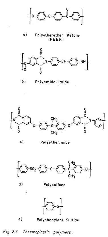
Although thermosets are commonly used in structural composites due to their higher strength and stiffness properties, there is a growing interest in recent years to use thermoplastics as well. The development of several high performance thermoplastics has been primarily responsible for this new trend. The main advantage with thermoplastic polymers is that they can be repeatedly formed by heat and pressure. A thermoplast is a collection of high molecular weight linear or branched molecules. It softens upon heating at temperature above the glass transition temperature, but regains its strength upon cooling. The increase in temperature activates the random motion of the atoms about their equilibrium positions and results in breakage of secondary bonds. The thermoplast softens and results in breakage of secondary bonds. The thermoplast softens and flows when pressure is also applied. When the temperature is lowered, new secondary bonds are formed and the polymer reverts to its original structure. The process of softening at higher temperature and regaining rigidity upon cooling is thus reversible in the case of a thermoplastic polymer. This characteristic behaviour helps it to be recast and reused several times. The repair of a damaged part also becomes simpler. The scrapage rate is also reduced. All these make thermoplasts very much cost effective. A thermoplastic polymer softens, but does not decompose unless the temperature is high enough to break the primary covalent bonds.
Table 2.4 provides the typical thermo-mechanical properties of a couple of structural grade thermoplastic resins. These high performance resins are thermally stable at higher temperatures. They normally achieve high glass transition temperature Tg due
Table 2.4 Typical properties of some high performance thermoplastics
|
Properties |
Polyether ether ketones (PEEK) |
Polyamide-imide |
Polyether-imide |
Polysulfone |
Polyphenylene sulfide |
|
Density, kg/m3 |
1300 |
1400 |
1270 |
1240 |
1340 |
|
Tensile strength, MPa |
104 |
138 |
115 |
70 |
76 |
|
Tensile modulus, GPa |
4.21 |
4.48 |
3.38 |
2.48 |
3.31 |
|
Poisson’s ratio |
0.35 |
0.35 |
0.35 |
0.35 |
0.35 |
|
Coefficient of thermal expansion, 10-6m/m K |
- |
56 |
50 |
86.40 |
88 |
|
Maximum service temperature, K |
630 |
- |
490 |
490 |
565 |
to their relatively stiff, linear chains and high molecular weight. They are also strong and stiff and exhibit good creep resistant properties. They are relatively tougher and less sensitve to moisture. The structures of these resins are illustrated in Fig. 2.7. All resins are found to contain a high proportion of aromatic rings that are linked by a stable heteroatom or group (-CO-, SO2-, -O-, etc.). This provides a high degree of chain rigidity and thereby results in a higher Tg. In addition, the low aliphatic hydrogen (C-H) content enhances the thermal stability of all these resins at high temperatures. PEEK and polyphenylene sulfide are essentially crystalline polymers, and other resins shown in Table 2.4 are amorphous. PEEK has received considerable attention since its inception. The rigid rings, connected by fairly chemically inert groups (-o- and –c-) make PEEK highly crystalline. The melting point and chemical resistance of PEEK are also considerably enhanced. PEEK has a Tg of 1430C and a melting point of 3320C. It is soluble only in concentrated sulphuric acid. The processing temperature ranges 300-4000C. The moisture absorption limit is very low. The fracture toughness is comparatively higher. All these features of PEEK make it a highly attractive thermoplastic resin for application in reinforced composites. Graphite/PEEK composite prepregs are commercially available. Polysulfones reinforced with glass, aramid and carbon fibres have also found several applications.
Thermoset polymers are formed from relatively low molecular weight precursor molecules. The polymerization process in a thermoset resin is irreversible. Once cured, they do not soften upon heating. They, however, decompose before softening upon further heating. Cross-linked and interlinked reactions lead to formation of chain molecules in two and three-dimension arrays. Because of three dimensional network of covalent bonds and cross links, thermosetting resins are listed in Table 2.5. At high temperature, the covalent bonds may break leading to destruction of the network structure and the polymer decomposes. Thermosetting resins vary widely with Tg values varying from 45-3000C and elongations ranging from 1% to more than 100%.
Table 2.5 Typical properties of some thermosetting resins
|
Properties |
Epoxies |
Polyesters |
Phenolics |
Polyimides |
|
Density, kg/m3 |
1100-1400 |
1200 |
1200-1300 |
1400 |
|
Tensile strength, MPa |
35-100 |
50-60 |
50-60 |
100-130 |
|
Tensile modulus, GPa |
1.5-3.5 |
2-3 |
5-11 |
3-4 |
|
Poisson’s ratio |
0.35 |
0.35 |
0.35 |
0.35 |
|
Coefficient of thermal expansion, 10-6m/mK |
50-70 |
40-60 |
40-80 |
30-40 |
|
Service temperature, K |
300-370 |
330-350 |
440-470 |
550-750 |
The most commonly used thermosets are epoxy, polyester and phenolic resins, among which polyster resins are most widely used in various common engineering goods and composite applications. However, epoxy resins constitute the major group of thermoset resins used in composite structures and adhesives, as they are stronger and stiffer. Phenolic resins are rich in carbon and possess good thermal properties and are normally used in high temperature applications especially as an ablative material in thermal protection systems. Silicone, bismaleimide, polyimide, polybenzimidazol, etc. are in fact, high temperature polymers that can perform at higher temperature ranging from 200-4500C. The structures of some thermosetting resins are illustrated in Fig. 2.8.
Epoxy resins in general possess good thermomechanical, electrical and chemical resistant properties. They are so called, because they contain two or more epoxide groups in the polymer before cross-linking. This epoxide group is a three membered cyclic ether
![]()
![]()
![]()
![]()
![]() O
O
![]()
![]() C C which reacts with several reagents. It is commonly found in
glycidyl ethers and amines which are the major sources for epoxies in composite
applications. The common epoxy is synthesized by condensing epichlorohydrin with
bisphenol A in the presence of sodium hydroxide. Several other
hydroxyl-containing compounds can replace bisphenol A. A wide variety or special
purpose resins can thus be prepared. Some aerospace grade epoxy systems are
based on an aromatic amine (glycidyl amines) instead of a phenol to increase the
epoxy functionality leading to high cross-link density in the cured resin. Epoxy
resins are cured using suitable curing agents or appropriate catalysts. The
major curing agents are aliphatic amines, aromatic polyamines and polyanhydrides.
Curing is the processs of reaction (ionic reaction, usually polyadditions)
between the epoxide and the curing agent in which many epoxide groups are
formed. Aliphatic amines are relatively strong bases and therefore react with
aromatic amines to achieve cure at room temperature. The reaction is highly
exothermic, and the pot life is shorter. This epoxy resin is useful for contact
moulding, but not for prepregging and filament winding. Aromatic polyamines are
normally solids and require high temperature (100-1500C) for mixing
and curing. Anhydrides need higher thermal exposure (150-2000C) for a
longer duration (8-16 hours) for proper curing. The reaction is low exothermic,
but the pot life is longer. Both polyamines and anhydrides are suitable for
prepreg manufacturing and filament winding. These epoxy resins are characterized
by comparatively high thermal stability and chemical resistance. Catalysts can
also be used along with curing agents to accelerate the curing process.
Catalytic agents that are often used as curing agents to promote
homopolymerisation of epoxide groups may be Lewis acids or bases. The commonly
used catalytic curing agent is boron trifluoride blocked with ethyl amine (a
typical Lewis acid). It is also used as a catalyst with aromatic amines to
accelerate curing at a temperature of 150-2000C. Lewis bases are
normally used as accelerators with anahydrides. Both Lewis acids and bases
provide long pot lives.
C C which reacts with several reagents. It is commonly found in
glycidyl ethers and amines which are the major sources for epoxies in composite
applications. The common epoxy is synthesized by condensing epichlorohydrin with
bisphenol A in the presence of sodium hydroxide. Several other
hydroxyl-containing compounds can replace bisphenol A. A wide variety or special
purpose resins can thus be prepared. Some aerospace grade epoxy systems are
based on an aromatic amine (glycidyl amines) instead of a phenol to increase the
epoxy functionality leading to high cross-link density in the cured resin. Epoxy
resins are cured using suitable curing agents or appropriate catalysts. The
major curing agents are aliphatic amines, aromatic polyamines and polyanhydrides.
Curing is the processs of reaction (ionic reaction, usually polyadditions)
between the epoxide and the curing agent in which many epoxide groups are
formed. Aliphatic amines are relatively strong bases and therefore react with
aromatic amines to achieve cure at room temperature. The reaction is highly
exothermic, and the pot life is shorter. This epoxy resin is useful for contact
moulding, but not for prepregging and filament winding. Aromatic polyamines are
normally solids and require high temperature (100-1500C) for mixing
and curing. Anhydrides need higher thermal exposure (150-2000C) for a
longer duration (8-16 hours) for proper curing. The reaction is low exothermic,
but the pot life is longer. Both polyamines and anhydrides are suitable for
prepreg manufacturing and filament winding. These epoxy resins are characterized
by comparatively high thermal stability and chemical resistance. Catalysts can
also be used along with curing agents to accelerate the curing process.
Catalytic agents that are often used as curing agents to promote
homopolymerisation of epoxide groups may be Lewis acids or bases. The commonly
used catalytic curing agent is boron trifluoride blocked with ethyl amine (a
typical Lewis acid). It is also used as a catalyst with aromatic amines to
accelerate curing at a temperature of 150-2000C. Lewis bases are
normally used as accelerators with anahydrides. Both Lewis acids and bases
provide long pot lives.
A polyester resin is comprised of an unsaturated backbone polymer dissolved in a reactive monomer. The polyester backbone polymer is formed by condensation of a mixture of diabasic acids (saturated and unsaturated) and one or more glycols. The components of the most commonly used polyester resin is phthalic anhydride (saturated acid), maleic anhydride (unsaturated acid) and propylene glycol. The backbone polymer is then diluted in styrene monomer (about 35% by weight). The solution is then blended with an inhibitor such as hydroquinone to prevent premature polymeisation. The process of curing is initiated by adding a source of free radicals (e.g., benzoyl peroxide or hydroperoxide and catalysts (e.g., organic peroxides such as cobalt naphthenate or alkyl mercaptans). Curing takes place in two stages: a soft gel is first formed and this is followed by a rapid polymerization with generation of heat. A higher proportion of unsaturated acid in the backbone polymer yields a more reactive resin, while with a higher quantity of saturated acid the reaction becomes less exothermic. During curing, the styrene monomer reacts with the unsaturated sites of the backbone polymer to form a three-dimensional cross-linked network. A small amount of wax is often added to the solution before curing to facilitate proper curing of the surface of a laminate. Wax, during curing, exudes to the surface to form a thin protective layer that reduces loss of styrene from the surface and prevents oxygen which inhibits reaction to come in contact with the radicals. Several types of polyester resins are commercially available. Vinyl-ester resins are high performance polyester resins, which are acrylic esters of epoxy resins dissolved in styrene monomer. Polyester resins can be reinforced with almost all types of reinforcements to make polyester composites. Polyester resins are cheaper and more versatile, but inferior to epoxy resins in some respects. Their use in advanced structural composites is therefore limited. However, they have been widely used in boat hulls, civil engineering structures, automobile industries and various engineering products and appliances.
The commonly used phenolic (phenol-formaldehyde) resins are divided into two groups: resoles and novolacs. Resoles are one-stage resins which are synthesized with formaldehyde/phenol ratio greater than one (1.25:1) in presence of an alkaline catalyst. The polymerization process is not fully completed. It is stopped by cooling to obtain a reactive and soluble polymer which is stored at low temperature. The final polymerization process is initiated, during curing, by raising the temperature. The novolacs, on the other hand, are two-stage resins, made with an acid catalyst. The ratio of formaldehyde to phenol is kept about 0.8:1. In the first stage, the reaction is completed to yield an unreactive thermoplastic oligomer which is dehydrated and pulverized. A curing agent such as hexamethylenetetramine is added in the second stage, which decomposes due to heat and moisture during final curing to yield formaldehyde and ammonia. The ammonia also acts as a catalyst for curing. Resoles are used for prepregs and structural laminates. Novolacs are normally used as moulding compounds and friction products. Phenolic resins, as a whole, provide good dimensional stability as well as excellent chemical, thermal and creep resistance, and exhibit low inflammability. Phenolics char when exposed to the high temperatures and form a layer of carbon which in turn protects the underlying composite from being exposed to high temperature. This characteristic behaviour has made phenolic resins as candidate materials in making reinforced composites for high temperature applications and thermal shielding.
Several high temperature thermosetting polymers are currently available, of which polyimides, bismaleimides, polybenzimidazole, silicone, etc. are of special interest to composite applications. Polyimides are made by polycondenstion of aromatic dianhydrides and aromatic diamines. The reaction between dianhydride and diamine (at a temperature lower than 1000C) first yields a soluble polyamic acid. Next cyclisation of the polyimides retain their usable properties at 3000C (continuous exposure) and can withstand an exposure of 5000C for a few minutes. Bismaleimides are addition polyimides. Silicone polymers are formed by intermolecular condensation of silanols which are produced from the halide or alkoxy intermediates. Both silicone and polybenzimidazole resins are normally used in the intermediate temperature range (200-2500C).
The reinforced plastics are very extensively used in engineering industries. Some important structural applications of fibre reinforced polymer composites are listed in Table 2.6.
Table 2.6: Applications fibre reinforced polymer composites
|
Composites |
Uses |
Aerospace |
|
|
CFRP |
Wing Skin, Front Fuselage, Control Surface Fin & Rudder, Access Doors, Under Carriage Doors, Engine Cowlings, Main Torsion Box, Fuel Tanks, Rotor Blades, Fuselage Structures and Floor Boards of Helicopters, Antenna Dishes, Solar Booms and Solar Arrays, etc. |
|
BFRP |
Horizontal and Vertical Tail, Stiffening Spars, Ribs and Longerons, etc. |
|
KFRP |
Nose Cones, Wing Root, Fairings, Cockpit and Fuselage of Helicopters, Motor Casings, Pressure Bottles, Propellant Tanks, Other Pressurised Systems, etc. |
|
GFRP |
Floor Boards, Interior Decorative Panels, Partitions, Cabin Baggage Racks and Several Similar Applications. |
Structural |
|
|
GFRP |
Folded Plates of Various Forms, Both Synclastic and Anticlastic Shells, Skeletal Structures, Walls and Panels, Doors, Windows, Ladders, Staircases, Chemical and Water Tanks, Cooling Towers, Bridge Decks, Antenna Dishes, etc. |
Marine and Mechanical |
|
|
GFRP |
Ship and Boat Hulls, Masts, Automobile Bodies, Frames and Bumpers, Bodies of Railway Bogeys, Drive shafts, Connecting Rods, Suspension Systems, Instrument Panels. |
Sports |
|
|
GFRP/CFRP |
Skis, Ski Poles, Fishing Rods, Golf Clubs, Tennis and Badminton Rackets, Hockey Sticks, Poles(Pole vault), Bicycle Frames, etc. |
2.4 METALS AND METAL MATRIX COMPOSITES
Polymer composites are used normally up to 1800C, but rarely beyond 3500C. The high temperature capabilities of inorganic reinforcements cannot be realized, when polymers are employed as matrix materials. Metal matrices, on the other hand, can widen the scope of using composites over a wide range of temperatures. Besides, metal matrix composites allow tailoring of several useful properties that are not achievable in conventional metallic alloys. High specific strength and stiffness, low thermal expansion, good thermal stability and improved wear resistance are some of the positive features of metal matrix composites. The metal composites also provide better transverse properties and higher toughness compared to polymer composites.
Table 2.7 provides the list of some metal matrices and associated reinforcing materials. The reinforcements can be in the form of either particulates, or short fibres or continuous fibres. Cermets constitute an important group of metal matrix composites in which ceramic grains of sizes greater than 1 µm are dispersed in the refractory metal matrix. A typical example is the titanium carbide cermet which comprises of 70% TiC particles and 30% nickel matrix and exhibits high specific strength and stiffness at very high temperatures. The thermo-mechanical properties of some common matrices are presented in Table 2.8. The aluminium matrices include several alloys such as AA 1100, AA 2014, AA6061, AA 7075, AA5052, etc. The composites with aluminium matrices are relatively lightweight, but their applications are limited to the lower temperature range
Table 2.7: Metal matrices and reinforcements
|
Matrix |
Reinforcements |
|
Aluminium and alloys |
C, Be, SiO2, B, SiC, Al2O3, Steel, B4C, Al3Ni, Mo, W, ZrO2 |
|
Titanium and alloys |
B, SiC, Mo, SiO2, Be,ZrO2 |
|
Nickel and alloys |
C, Be, Al2O3,SiC, Si3N4, steel, W, Mo, B |
|
Magnesium alloys |
C, B, glass, Al2O3 |
|
Molebdenum and alloys |
B, ZrO2 |
|
Iron and Steel |
Fe, Steel, B, Al2O3, W, SiO2,ZrO2 |
|
Copper and alloys |
C,B, Al2O3, E-glass |
Table 2.8: Typical thermomechanical properties of some metal matrices
|
Matrices
|
Density kg/m3 |
Tensile strength MPa |
Tensile modulus GPa |
Coefficient thermal expansion 10-6m/mk |
Thermal conduct- -vity W/(mk) |
Heat capa- -city KJ/ (kg.k) |
Melting point 0C |
|
AA6061 |
2800 |
310 |
70 |
23.4 |
171 |
0.96 |
590 |
|
Nickel |
8900 |
760 |
210 |
13.3 |
62 |
0.46 |
1440 |
|
Ti-6AL-4V |
4400 |
1170 |
110 |
9.5 |
7 |
0.59 |
1650 |
|
Magnesium |
1700 |
280 |
40 |
26 |
100 |
1.00 |
570 |
|
Steel |
7800 |
2070 |
206 |
13.3 |
29 |
0.46 |
1460 |
|
Copper |
8900 |
340 |
120 |
17.6 |
391 |
0.38 |
1080 |
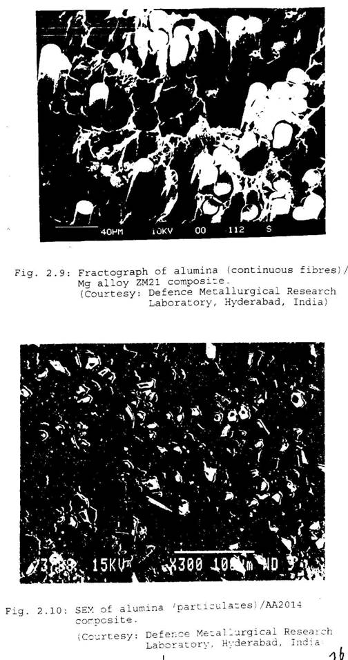
because of its low melting point. Titanium and nickel can be used at a service temperature of up to 1000-11000C. There are several systems such as engine components which are exposed to high level of temperature. Titanium and nickel composites are ideal for such situations, as they retain useful properties at 1000-11000C. Ti-6AL-4V is the commonly used titanium matrix material. The other alloys of titanium include A-40Ti, A-70Ti, etc. Nickel matrices are comprised of a series of Ni-Cr-W-Al-Ti alloys. Super alloys, NiCrAlY and FeCrAlY, are also used as matrices because of their high oxidation resistance properties. Molybdenum is a high temperature matrix and fibre material. Iron and steel matrices are cheaper and can be used at high temperatures, if the weight is not the major concern. Figure 2.9 exhibits a fractograph of the Al2O3 fibre reinforced Mg alloy ZM21 composite. A scanning electron micrograph of the Al2O3 fibre reinforced AA 2014 composite is shown in Fig. 2.10.
The high temperature applications of metal matrix composites are listed in Table 2.9. The material cost is the major problem that currently limits their uses, otherwise most of the metallic structural parts can be replaced with metal matrix composite parts to gain advantages.
Fig.2.9
Fig.2.10
Table 2.9: High temperature application of composites
|
Composites |
Applications |
|
MMCs |
Aeroengine Blades, Combustion Chamber, Thrust Chamber, Nozzle Throat, Exit Nozzle, Engine Valves, Fins. |
|
CMCs |
Re-entry Thermal Shields and Tiles, Nozzle Throat, Nozzle Linings, Pump Seal Rings, Break Linings, Extrusion Dies, Valves, Turbochargers, Turbine Blades, Cutting Tools |
|
Carbon-Carbon |
Nose Cones of Re-entry Vehicles, Combustion and Thrust Chambers, Nozzle Throats, Exit Nozzles, Leading Edges of Re-entry Structures, Brake Discs. |
Ceramic provide strength at high temperature well above 15000C and have considerable oxidation resistance. They possess several desirable attributes like high elastic modulus, high Peierl`s yield stress, low thermal expansion, low thermal conductivity, high melting point, good chemical and weather resistance as well as excellent electromagnetic transparency. However, the major drawback of ceramics is that they exhibit limited plasticity. This low strain capability of ceramics is of major concern, as it, quite often, leads to catastrophic failure. For this reason ceramics are not considered as dependable structural materials. But such limitations may not exist with ceramic matrix composites, as suitable reinforcements may help them to achieve desirable mechanical properties including toughness. The ceramic matrices are usually glass, glass ceramics (lithium aluminosilicates), carbides (SiC), nitrides (SiN4, BN), oxides (Al2O3, Zr2O3, Cr2O3, Y2O3, CaO, ThO2) and borides (ZrB2, TiB2). The reinforcements which are normally high temperature inorganic materials including ceramics, may be in the form of particles, flakes, whiskers and fibres. The commonly used fibres are carbon, silicon carbide, silica and alumina. The current resurgence in the research and development of ceramic matrix composites is due to their resistance to wear, creep, low and high cycle fatigue, corrosion and impact combined with high specific strength at high temperatures. The cutting rate of an alumina-SiC whisker cutting tool is ten times higher than that of conventional tools. The use of ceramic composites in aero-engine and automotive engine components can reduce the weight and thereby enhance the engine performance with higher thrust to weight ratios due to high specific strength at high temperatures. Automotive engines exhibit greater efficiency because of their low weight, better performance at high operating temperatures and longer life time due to excellent resistance to heat and wear. Several high temperature applications of ceramic matrix composites are presented in Table 2.9.
Carbon-carbon composites are the most important class of ceramic matrix composites that can withstand temperatures as high as 30000C. They consist of carbon fibres distributed in a carbon matrix. They are prepared by pyrolysis of polymer impregnated carbon fibre fabrics and preforms under pressure or by chemical vapour deposition of carbon or graphite. The polymers used are of three types: thermosets (furfurals, phenolics), thermoplastic pitches (coal tar based and petroleum based) and carbon-rich vapours (hydrocarbons such as methane, propane, acetylene, benzene). Phenolic resins are more commonly used in the manufacturing process of carbon-carbon composites. The phenolic resin impregnated carbon fibre preforms, on pyrolysis, converts the phenolic resin to a high proportion of amorphous carbon char. The composite material is found to be porous after the first pyrolysis. It is further impregnated with the phenolic resin and pyrolised, usually under vacuum and pressure, and the process is repeated several times to reduce the void content and realize the optimum density of the material. The major advantage of carbon-carbon composite is that various fabrics and shapes of preforms with multidirectional fibre alignments can be impregnated with resins and pyrolised to yield a wide class of one directional (1D), two directional (2D), three directional (3D) and multidirectional composite blocks of various shapes and sizes, which can be machined to produce the desired dimensions. Excellent wear resistance, higher coefficient of friction with the rise of temperature, high thermal conductivity, low thermal expansivity and high temperature resistance make them useful materials in high temperature applications. In absence of oxygen, carbon-carbon composites can withstand very high temperatures (30000C or more) for prolonged periods. They are also used in prosthetics due to excellent biocompatibility.
The structural applications of composites are mostly in the form of laminates. Laminates provide the inherent flexibility that a designer exploits to choose the right combination of materials and directional properties for an optimum design. A lamina is the basic building block in a laminate. A lamina may be made from a single material (metal, polymer or ceramic) or from a composite material. A composite lamina, in which all filaments are aligned along one direction parallel to each other, is called a unidirectional lamina. Some unidirectional laminae are illustrated in Fig. 2.11. Here the fibres (continuous) are oriented along a direction parallel to the x1 axis. Note that the x1', x2' axes are the material axes, and the x1, x2 axes are the reference axes. The orientation of the fibre with respect to the reference axis (i.e., x1 axis) is known as the fibre angle and is denoted by Ø (in degrees). A unidirectional lamina is designated with respect to the fibre angle Ø. For example, a 00 lamina corresponds to Ø=00, a 900 lamina corresponds to Ø=900 and so on.
Fig. 2.11
A laminate is designated by the manner laminae are stacked to form the laminate. For example, a (00/±450/900) laminate (Fig. 2.12) is one in which one 00 lamina is placed at the top, one 900 lamina is placed at the bottom and one +450 lamina and one -450 lamina are kept at the middle. Unless it is specified, it is normally assumed that all the laminae in a laminate possess the same thickness. A cross-ply laminate consists of only 00 and 900 laminae. An angle-ply laminate, on the other hand, contains only ±Ø laminae. A laminate may be considered symmetric, antisymmetric or unsymmetric, in case there exists, with respect to the middle surface, any symmetry, antisymmetry or unsymmetry, respectively. Figures 2.13 and 2.14 illustrate several cross-ply and angle-ply laminates. It should be further noted that a [ (00/900)n ] laminate is an antisymmetric cross-ply laminate consisting of n numbers of repeating two-layered (00/900) cross-ply laminates. The total number of laminae in a [ (00/900)n ] laminate is 2n. However, a [ (00/900)ns ] laminate is a symmetric cross-ply laminate. It has symmetry about the midsurface of the laminate. The top half of the laminate contains n number of repeating of repeating two-layered (00/900) cross-ply laminates. The bottom half consists of n number of two-layered (900/00) cross-ply laminates so that the symmetry about the mid-surface is maintained. Note that the subscript `s` stands for symmetry and the number of laminae in a [ (00/900)ns] laminate is 4n. The laminates containing repeating (±Ø) angle-plies can also be identified in a similar way.
A general unsymmetric laminate may contain 00 laminae, 900 laminae and/or Ø laminae stacked in an arbitrary manner. For example, [ (00)4 / (900)2], [(900)2/ (300)2] and [00/900/300/600] are all general unsymmetric laminates. An unsymmetry may also be introduced by stacking laminae made of different composites. A [00c/900g /00k] laminate consists of a top layer of 00 carbon fibre reinforced composite, a middle layer of 900 glass fibre reinforced composite and bottom layer of 00 Kevlar fibre reinforced composite and is an unsymmetric cross-ply hybrid laminate. Various such hybrid laminates can be prepared for practical applications choosing various combinations of layers of metallic materials, polymer composites, metal-matrix composites and ceramic composites. The “ARALL” is a hybrid laminate consisting of alternate layers of aramid/epoxy composite and aluminium alloys. Aramid epoxy composites are commonly combined with carbon epoxy composites to make carbon-kevlar hybrid composites to obtain a cost effective composite with superior compressive and impact resistant properties. Kevlar fibres are inexpensive compared to carbon fibres and are effective in resisting the impact forces. Carbon fibres, in turn, improve the compressive strength in the carbon-kevlar hybridization.
1. Why fibres are preferred to other reinforcements ? What are whiskers ? Describe how fibres are fabricated using vapour deposition processes.
2. What are carbon-carbon composites and how they are produced ?
Why they are recommended for high temperature applications ?
3. Write a note on metal matrix composites.
4. Write a note on ceramic matrix composites.
5. Describe the characteristics of a couple of thermosets and thermoplastics that are used for making composites for aerospace applications.
6. Why Kevlar fibres are recommended for strength and impact based structural designs? What are the basic differences between organic and other fibres ?